horizontal position (see illustration). On the
alternative type headlight units, the two
diametrically opposite screws are used for
adjustment. The upper screw adjusts the
horizontal setting and the lower screw adjusts
the vertical setting.
2 The lights should be set so that on full or
high beam, the beams are set slightly below
parallel with a level road surface. Do not
forget that the beam position is affected by
how the car is normally loaded for night
driving, and set the beams with the car loaded
to this position.
3 Although this adjustment can be
approximately set at home, it is
recommended that beam alignment is be
carried out by a Rover dealer or other
specialist heaving the necessary optical
alignment equipment.
8 Dim-dip lighting system
components - removal and
refitting
1
Dim-dip unit
Removal
1 Remove the instrument panel as described
in Section 15.
2 Disconnect the dim-dip unit from the wiring
loom connector (see illustration).
Refitting
3 Refitting is the reverse sequence to
removal.
Dim-dip resistor
Removal
4 Disconnect the battery negative lead.
5 Open the bonnet, and unclip the wiring
loom connector on the right-hand side of the
engine compartment (see illustration).
6 Pull the resistor plug from the connector,
and release the wiring loom.
7 Unscrew the mounting bolt, and withdraw
the resistor and mounting plate.
Refitting
8 Refitting is the reverse sequence to
removal.
9 Horn - removal, refitting and
adjustment
2
Removal and refitting
1 The horn is located in the engine
compartment and is attached to a bracket,
which is in turn secured to the front body
panel by two small nuts and bolts (see
illustration).
2 To remove the unit, disconnect the horn
wiring then undo the retaining bracket nuts
and bolts. Remove the horn, complete with
bracket, then remove the bracket. The horn is
not repairable and should not be dismantled.
3 Refitting is the reverse sequence to
removal.
Adjustment
4 On early type horns an adjustment is
provided to compensate for wear of the
moving parts.
5 Adjustment is by means of a screw on the
broad rim of the horn nearly opposite the two
terminals. Do not confuse this with the large
screw in the centre.
6 Turn the adjustment screw anti-clockwise
until the horn just fails to sound. Then turn the
screw a quarter of a turn clockwise, which is
the optimum setting.
Body electrical system 12•11
12
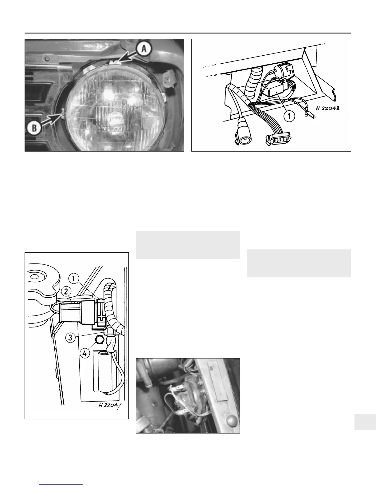
9.1 Horn location showing electrical leads
and mounting nuts
7.1 Headlight vertical position A and horizontal position B
adjusting screws
8.2 Location of dim-dip lighting unit (1) behind the
instrument panel
8.5 Location of dim-dip resistor
1 Wiring loom
connector
2 Resistor plug
3 Wiring loom clip
4 Mounting plate
bolt
 Loading...