Mini Cooper, 1275 cc, (12A) 1990-on
Carburettor type . . . . . . . . . . . . . . . . . . . . . . . . . . . . . . . . . . . . . . . . . . . SU HIF44
Piston spring . . . . . . . . . . . . . . . . . . . . . . . . . . . . . . . . . . . . . . . . . . . . . . Red
Jet size . . . . . . . . . . . . . . . . . . . . . . . . . . . . . . . . . . . . . . . . . . . . . . . . . . 2.5 mm
Needle . . . . . . . . . . . . . . . . . . . . . . . . . . . . . . . . . . . . . . . . . . . . . . . . . . . BFY
Idle mixture CO % . . . . . . . . . . . . . . . . . . . . . . . . . . . . . . . . . . . . . . . . . 1.6 to 3.0 (measured at gas sampling pipe)
Idle speed . . . . . . . . . . . . . . . . . . . . . . . . . . . . . . . . . . . . . . . . . . . . . . . . 900 rpm
Fast idle speed . . . . . . . . . . . . . . . . . . . . . . . . . . . . . . . . . . . . . . . . . . . . 1200 ± 50 rpm
Mini Saloon and variants, 1275 cc (12A) 1992-on
Carburettor type . . . . . . . . . . . . . . . . . . . . . . . . . . . . . . . . . . . . . . . . . . . SU HIF38
At the time of writing, no further specifications were available for this model.
Recommended fuel
Minimum octane rating (see text Section 10):
All pre-1989 models* . . . . . . . . . . . . . . . . . . . . . . . . . . . . . . . . . . . . . 97 RON leaded
1989-on, 998 cc low-compression models . . . . . . . . . . . . . . . . . . . . 95 RON unleaded or 90 RON leaded
1989-on, 998 cc high-compression models . . . . . . . . . . . . . . . . . . . . 95 RON unleaded or 97 RON leaded
1990-on 1275 cc (12A) models . . . . . . . . . . . . . . . . . . . . . . . . . . . . . . 95 RON unleaded only
*Pre-1989 models with a “Green pack” can be run on 95 RON unleaded petrol - see text for further information.
Note: Models with a catalytic converter must be run on unleaded petrol only.
Torque wrench setting Nm lbf ft
Manifold retaining nuts . . . . . . . . . . . . . . . . . . . . . . . . . . . . . . . . . . . . . . 22 16
1 General information and
precautions
General information
The fuel system comprises a fuel tank, an
electric or mechanical fuel pump and a
variable choke carburettor.
The fuel tank is located in the luggage
compartment on Saloon models, and beneath
the rear floor on the Estate, Van and Pick-up
variants. On Cooper S versions twin fuel tanks
are used, these being positioned on either
side of the luggage compartment.
A number of the earlier vehicles covered by
this manual are equipped with an SU electric
fuel pump which is mounted on the left-hand
member of the rear subframe. All later Mini
models utilise a mechanical fuel pump bolted
to the rear of the engine and operated by an
eccentric on the camshaft.
A variable choke carburettor of SU
manufacture is fitted to all models. Manual
transmission versions manufactured up to
1974 utilise a single SU HS2 unit, the
exception to this being the Cooper S model
which incorporates a twin carburettor
installation. Later vehicles are equipped with
the larger SU HS4 carburettor, or its
derivatives the HIF38 and HIF44. Further
information on carburettor types will be found
later in this Chapter.
Certain models are fitted with emission
control equipment to reduce the level of
harmful emissions in the exhaust gases.
Information on the exhaust and emission
control systems is contained in Part C of this
Chapter.
Precautions
Warning: Petrol is extremely
flammable - great care must be
taken when working on any part
of the fuel system. Do not smoke
or allow any naked flames or uncovered
light bulbs near the work area. Note that
gas powered domestic appliances with
pilot flames, such as heaters, boilers and
tumble dryers, also present a fire hazard -
bear this in mind if you are working in an
area where such appliances are present.
Always keep a suitable fire extinguisher
close to the work area and familiarise
yourself with its operation before starting
work. Wear eye protection when working
on fuel systems and wash off any fuel spilt
on bare skin immediately with soap and
water. Note that fuel vapour is just as
dangerous as liquid fuel; a vessel that has
just been emptied of liquid fuel will still
contain vapour and can be potentially
explosive. Petrol is a highly dangerous and
volatile liquid, and the precautions
necessary when handling it cannot be
overstressed.
Many of the operations
described in this Chapter involve
the disconnection of fuel lines,
which may cause an amount of
fuel spillage. Before commencing work,
refer to the above Warning and the
information in “Safety first” at the
beginning of this manual.
When working with fuel system
components, pay particular
attention to cleanliness - dirt
entering the fuel system may cause
blockages which will lead to poor running.
2 Air cleaner assembly -
removal and refitting
1
All models except Cooper,
and 1992-on models with
open-loop catalytic converter
Removal
1 Undo and remove the single wing nut and
washer on early models, or the twin wing bolts
and washers on later models, securing the air
cleaner to the carburettor (see illustrations).
2 If the air cleaner is retained by a single wing
nut lift off the air cleaner top cover. Detach the
rocker cover hose, then lift the air cleaner
body off the carburettor, tip it up at the front
and slide it sideways until it is clear of the long
retaining stud and can be lifted away. Recover
the sealing ring (see illustrations).
Fuel system - carburettor engines 4A•3
4A
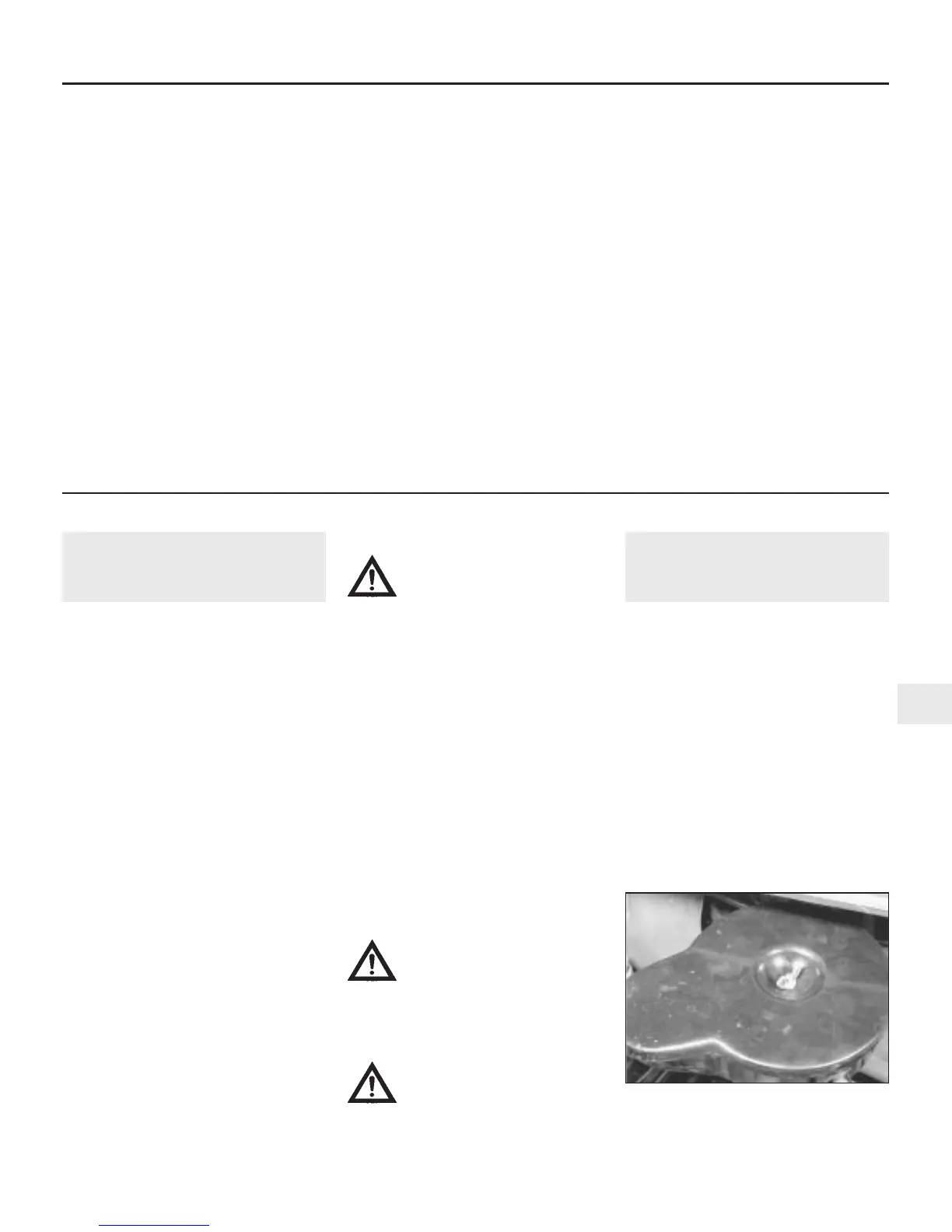
2.1a Remove the single wing nut on early
models . .
 Loading...