Do you have a question about the Hayward GLX-FLO and is the answer not in the manual?
Details the GLX-FLO as a normally open flow switch for pool and spa applications.
Outlines switch type, flow rates for 1½" and 2" pipe, and electrical rating.
General guidance for mounting the flow switch in a tee fitting and ensuring proper pipe run.
Connects the flow switch to Hayward chlorination products for different system versions.
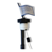
The GLX-FLO is a normally open flow switch designed for use in pool and spa applications. It is supplied with a 2-inch tee fitting, making it suitable for systems utilizing 1½-inch to 2-inch PVC pipe. The primary function of this switch is to detect water flow; it will close its circuit when the flow rate exceeds 10-12 gallons per minute (gpm). This flow detection capability is crucial for ensuring the proper operation of various pool and spa equipment, particularly chlorination systems, by confirming that water is actively circulating before allowing certain functions to engage.
For installation, the flow switch comes pre-mounted in a 2-inch tee fitting, simplifying the initial setup. If your piping is 1½ inches, adapters (which are not included) will be necessary to ensure a secure fit. To guarantee accurate operation, it is essential to allow for at least 12 inches of straight pipe run before the GLX-FLO. This straight section helps to stabilize the water flow, preventing turbulence that could lead to inaccurate readings or intermittent switch activation. During installation, users must pay close attention to the directional arrows located on both the tee and the flow switch itself. These arrows indicate the correct orientation for the water flow, and aligning them properly is critical for the switch to function as intended. If the flow switch ever needs to be removed from the tee for maintenance or replacement, it is important to apply Teflon tape to the threads when reinstalling it. This ensures a watertight seal and prevents leaks. Additionally, there are three arrows on the hex of the flow switch that must also point in the direction of the water flow, serving as a secondary visual check for correct orientation.
The wiring of the GLX-FLO is designed for ease of integration with Hayward chlorination products manufactured in May 2000 or later (date code 0005xxxx or later). The enclosed flow switch features a "phone jack" style connector, allowing for a simple plug-and-play connection into the appropriate receptacle on compatible Hayward equipment. This design streamlines the wiring process, reducing the potential for errors and making installation quicker for newer systems.
For Aqua Rite systems produced before May 2000, a slightly different wiring procedure is required due to the absence of the "phone jack" style connector. In these cases, the user will need to cut off the phone jack from the flow switch cable. After cutting the jack, the gray outer jacket of the cable should be stripped back approximately 1½ inches to expose the internal wires. The black and yellow leads within the cable are not used for these older systems and should be cut off. The insulation on the red and green leads then needs to be stripped to prepare them for connection. Finally, these red and green leads are connected to the flow switch terminals on the Aqua Rite low voltage terminal strip. This manual wiring process ensures compatibility with legacy systems, allowing the GLX-FLO to be integrated even with older Hayward equipment that predates the standardized phone jack connector.
Maintenance of the GLX-FLO primarily involves ensuring its correct orientation and proper sealing. The use of Teflon tape during reinstallation is a key maintenance step to prevent leaks. Regular checks of the directional arrows on both the tee and the flow switch hex can help confirm that the unit remains correctly aligned with the water flow, which is crucial for its consistent performance. While the manual does not detail specific cleaning procedures, ensuring that the pipe run leading to the switch is free of debris can help prevent blockages that might impede flow or interfere with the switch's operation. The robust design of the flow switch, intended for continuous use in pool and spa environments, suggests that with proper installation and occasional visual checks, it should provide reliable service. The emphasis on using only Hayward genuine replacement parts further underscores the importance of maintaining the system's integrity and performance with components designed to meet the manufacturer's specifications. This approach helps to ensure the longevity and efficiency of both the flow switch and the overall pool/spa system it supports.
| Manufacturer | Hayward |
|---|---|
| Model | GLX-FLO |
| Connection Type | Threaded |
| Category | Switch |
| Type | Flow Switch |
| Application | Pool |
| Voltage Rating | 120V AC |
| Material | Plastic |
| Compatibility | Hayward Pool and Spa Systems |