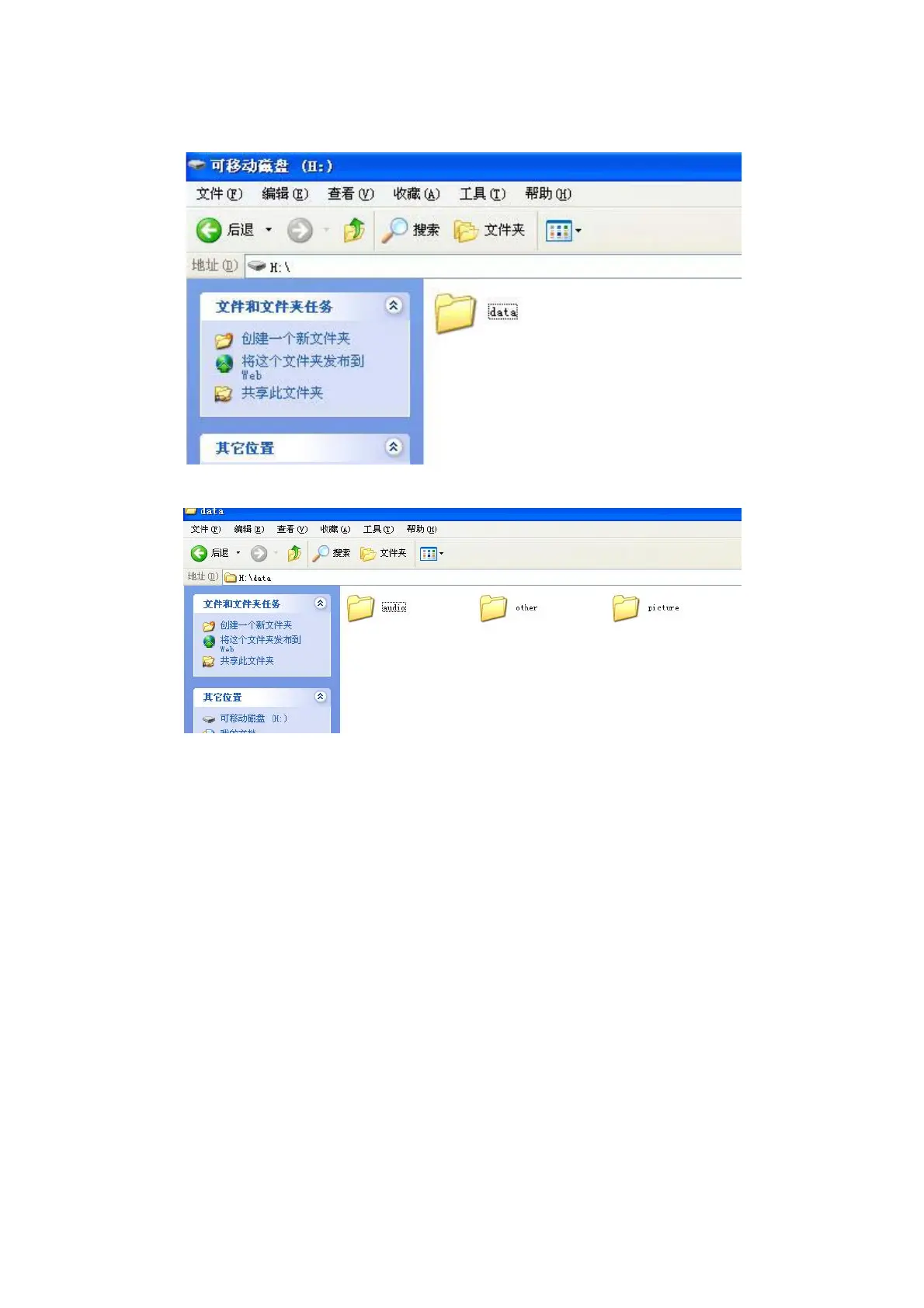
When format is ok, please build the “data” folder into the CF card.
There should build “audio” folder, “other” folder and “picture” folder under the “data” folder.
2.2PowerAlert
Please note there is four foot for the PSU output. And foot 4 is GND. And the power is foot 2. Usually the voltage
between foot 4 and foot 2 is DC24V. The system could not be started if this voltage is 0V.
The voltage for foot 1 and foot 3 rules as below:
1 When the AC appears on the Remote Alarm Panel:
Foot 1: DC24V;
Foot 2: DC24V;
Foot 3: DC0V;
2 When the ShIPDC appears on the Remote Alarm Panel;
Foot 1: DC24V;
Foot 2: DC24V;
Foot 3: DC24V;
 Loading...