2
INSTALLATION
Mounting the Controller
• The SPC is designed to mount on a 1900 (4”x4”) electrical box.
• If the SPC is to be panel mounted, or if additional room is needed for wiring, an extension skirt is available*.
• Locate the SPC in a convenient location near the unit to be controlled.
• Mount the unit away from excessive heat or cold. Ambient operating temperature is from 20 to 120°F.
• After completing all the wiring connections (see below) use the two screws provided to mount the SPC to the 1900 box.
Installing the Temperature Sensor
• The temperature sensor wires can be extended up to 500’ by splicing with 18 gauge shielded wire.
• Do not run wires in conduit with line voltage.
• If measuring liquid temperature, the sensor should be inserted into a 3/8” ID well (HT#904011 or equivalent).
• The SPC will operate based on the temperature it reads at the sensor location. Therefore, select a sensor location which is
representative of the entire system.
Wiring the Sensor
• The sensor wires can be connected to the two screws on the front of the SPC marked SENSOR.
• The wires can also be connected to the rear of the SPC using the Rear Wire connector*. Connect the sensor wires to the
orange and yellow wires from the Rear Wire connector.
• Polarity is not important. Either wire from the sensor can be connected to either SPC sensor input.
Wiring the Power - SPC can use either 120VAC, 24VAC, or 12VDC
120VAC
• Attach line voltage to the two blue wires extending from the back of the SPC.
• Use wire nuts, or wrap the connections with electrical tape.
• Class 1 voltages must enter the enclosure through a different opening from any Class 2 wiring.
24VAC
• Use a dedicated transformer with at least a 5VA output.
• Bring 24VAC to the two screws on the front of the SPC marked 24VAC
• 24VAC can also be connected to the rear of the SPC using the Rear Wire connector*. Connect the 24VAC to the violet and
gray wires from the Rear Wire connector.
12VDC
• The polarity of the connection is important. If the polarity is reversed, the SPC will not be damaged. However, it will not
operate unless the polarity is corrected.
• Bring the (+) side of the 12VDC to the inner screw marked 24VAC (see front page). Bring the (-) side of the 12VDC to the
outer screw marked 24VAC.
• 12VDC can also be connected to the rear of the SPC using the Rear Wire connector*. The (+) side of the 12VDC must be
connected to the connector’s violet wire. The (-) side of the 12VDC must be connected to the connector’s gray wire.
RED
WHITE
BLACK
24 VAC
12VDC
or wire 120VAC to rear
transformer (Blue Wires)
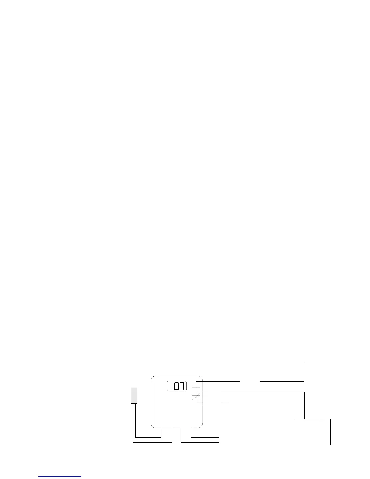
SENSOR
UNIT
POWER
NEUTRAL
HOT
TYPICAL WIRING DIAGRAM
HEATER
or CHILLER
UNIT
WARNING
The SPC can accept only one
source of power: 120VAC,
24VAC, or 12VDC. If more than
one power source is applied, the
unit may be damaged.
* The Optional Mounting Kit
includes the extension skirt,
the Rear Wire connector, and
an input terminal cover. Order
separately as HT #908520.
 Loading...