EasyManuals Logo

Heathkit DX-40 User Manual

Heathkit DX-40
20 pages
To Next Page IconTo Next Page
To Previous Page IconTo Previous Page
Page #3 background imageLoading...
Page #3 background image
INTRODUCTION
The
Heathkit
Transmitter
Model
DX-40
was
designed
to
permit
maximum
versatility
at
a
reason-
able
price.
It
features
up
to
“15
watts
input
with
three
switch-selected
crystal
positions
for
the
novice
operator.
It
includes
controlled
carrier
phone
operation
and
provision
for
VFO
excitation
for
the
general
class
ham.
It
has
sufficient
output
to
drive
larger
transmitters
when
the
station
is
expanded,
yet
is
small
enough
for
field
day
operation.
The
DX-40
consists
of
one
power
supply,
three
radio
frequency
stages,
and
two
dual-triode
audio
stages.
Pi
network
output
coupling
is
used
to
facilitate
antenna
matching.
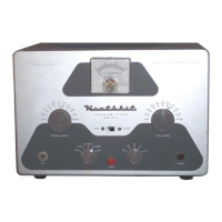
The
panel
con-
trols
consists
of
a
key
jack,
operation
switch,
band
switch, drive
control,
pilot
light,
final
tuning,
meter
switch
and
antenna
tuning.
The
mike
connector,
crystal
switch,
output
connector,
VFO
input
and
auxiliary
power
socket
are
located
on
the
rear
chassis
apron.
The
following
block
diagram
and
circuit
description
will
give
the
builder
abetter
understanding
of
the
transmitter.
This
knowledge
is
aninvaluable
aid
to
construction
and
as
such
is
well
worth
reading
thoroughly.
LETHAL
VOLTAGES
ARE
PRESENT
AT
MANY
POINTS
ABOVE
AND
BE-
LOW
THE
CHASSIS.
CONSEQUENTLY,
GREAT
CARE
MUST
BE
EXERCISED
WHEN
ANY
TEST
OR
ADJUSTMENTS
ARE
MADE.
6CL6
6146
an
FINAL
12Ax7
=
6
DE7
il
CARRIER
CONTROL
sMPUFIER
AND
CIRCUIT
DESCRIPTION
OSCILLATOR:
A
6CL6
tube
is-operated
in
a
Colpitts
circuit
to
provide
efficient
harmonic
out-
put
for
use
on
the
high
frequency
bands.
The
plate
tank
circuit
consists
solely
of
a
slug-tuned
coil
which
is
broadly
resonant
on
40
meters
but
serves
as
a
radiofrequency
choke
on
80
meters.
For
operation
on
80
through
10
meters
the
oscillator
plate
circuit
tunes
to
40
meters.
Pi
NETWORK
ANTENNA
COUPLING
6CLE
OSCILLATOR
KEY
Figure
1
MIKE
INPUT
wou
Three
crystals
may
be
switched
into
the
circuit
by
means
of
a
double-pole
switch
which
breaks
both
connections
to
the
crystals
to
prevent
interaction.
In
the
fourth
position,
the
6CL6
grid
is
connected
to
a
jack
for
external
VFO
control
and
the
cathode
RF
choke
is
bypassed
to
ground.
Plate
and
screen
voltage
for
the
oscillator
stage
are
derived
from
the
buffer
stage.cathode:
The
two
6CL6
tubes
are
operated
in
series
across
the
600
volt
supply
and
receive
approximately
300.
volts
each.
This
eliminates
the
necessity
of
power-wasting
dropping
resistors.
The
6CL6
buffer
in
most
cases,
tunes
the
second,
third,
or
fourth
harmonic
to
obtain
the
de-
sired
frequency.
Because
the
RF
level
required
by
the
buffer
stage
is
quite
low,
80
or
160
meter
crystals
may
be
used
for
output
on
80
without
the
necessity
of
resonating
the
oscillator
stage
plate
circuit
to
these
frequencies.
Page
3

Other manuals for Heathkit DX-40

Questions and Answers:

Question and Answer IconNeed help?

Do you have a question about the Heathkit DX-40 and is the answer not in the manual?

Heathkit DX-40 Specifications

General IconGeneral
BrandHeathkit
ModelDX-40
CategoryTransmitter
LanguageEnglish

Related product manuals