Page
6
START
-4
41-
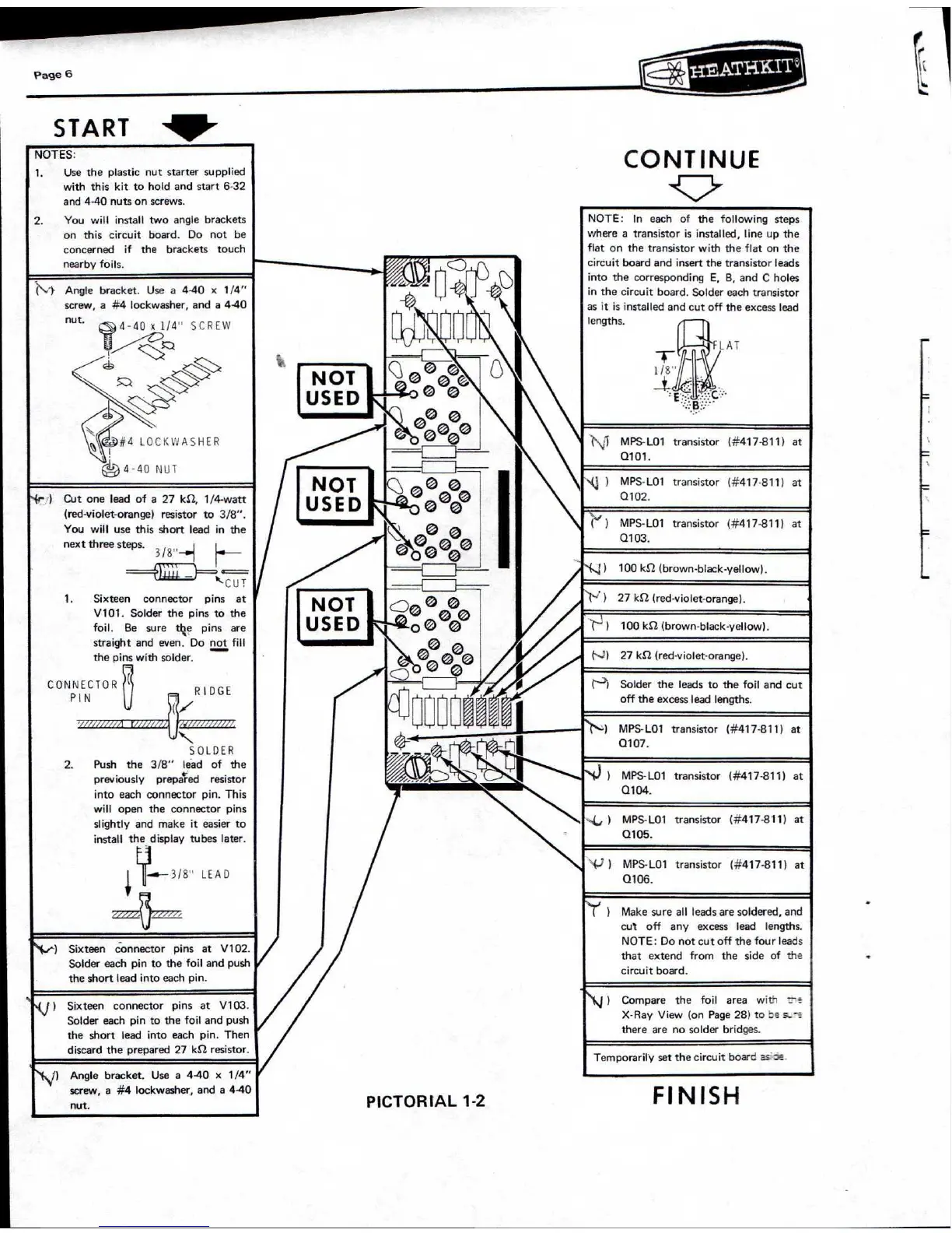
NOTES:
1.
Use the plastic nut starter supplied
with this kit to hold and start 6-32
and 4-40 nuts on screws.
2.
You will install two angle brackets
on
this circuit
board.
Do
not be
concerned
if
the
brackets
touch
nearby foils.
(
)
Angle bracket.
Use a 4-40
x
1/4"
screw, a #4 lockwasher, and a 4.40
nut.
4-40 x 1/4"
SCREW
<:6
-\
,7
#4 LOCKWASHER
6
4 -40 NUT
{,- )
Cut one lead of a 27 kfl, 1/4-watt
(red-violet-orange)
resistor to 3/8".
You will use this short lead in the
next three steps.
3/8
k
L. U T
1.
Sixteen
connector
pins
at
0
V101. Solder the pins to the
foil.
Be
sure
tge
pins
are
straight and even. Do not fill
the pins with solder.
CONNECTOR
PIN
RIDGE
NW/
AM/ /17112
1WM.1 .1
N
SOLDER
2.
Push
the
3/8"
lead
of
the
previously prepa
e
ed resistor
into each connector pin. This
will open the connector pins
slightly and make it easier to
install the display tubes later.
-0-3/8'
LEAD
Sixteen
connector
pins
at
V102.
Solder each pin to the foil and push
the short lead into each pin.
,J
)
Sixteen
connector
pins
at
V103.
Solder each pin to the foil and push
the short lead into each pin. Then
discard the prepared 27 kS2 resistor.
)
Angle bracket. Use a 4-40
x
1/4"
screw, a #4 lockwasher, and a 4-40
nut.
CONTINUE
NOTE:
In
each
of
the following steps
where a transistor is installed, line up the
flat on the transistor with the flat on the
circuit board and insert the transistor leads
into the corresponding E, B, and C holes
in the circuit board. Solder each transistor
as it is installed and
lengths.
-
4
---
cut
off the excess lead
FLA i
1/8
\
.
.
'..j
MPS-L01
transistor
(#417-811)
at
Q101.
NQ 1
MPS- LO1
transistor
(#417-811)
at
Q102.
)
MPS-L01
transistor
(#417-811)
at
Q103.
'4.„:1
100 Id2 (brown-black-yellow).
l'
-
: )
27 kS2 (red-violet-orange).
■
r )
100 k2 (brown-black-yellow).
(--')
27 kS2 (red-violet-orange).
---)
Solder the leads to the foil and cut
off the excess lead lengths.
/
MPS- LO1
transistor
(#417-811)
at
Q107.
1
MPS- LO1
transistor
(#417-811)
at
0104.
4.,
)
MPS-L01
transistor
(#417-811)
at
Q105.
4; 1
MPS-L01
transistor
(#417-811)
at
Q106.
,....,
(
)
Make sure all leads are soldered, and
cut
off
any
excess
lead
lengths.
NOTE: Do not cut off the four leads
that extend
from
the side of the
circuit board.
1
Compare
the
foil
area
w!th
t.
-
e.
X-Ray View (on Page 28) to ze..7„. --a
there are no solder bridges.
Temporarily set the circuit
boar:: :
-
...:_= ::-
,
2
FINISH
PICTORIAL 1-2
NOT
USED
NOT
USED
NOT
USED
r
•
--
-
1
H-
•
 Loading...