START
'W"
STEP-BY-STEP ASSEMBLY
4"
I
3
3
4
1/
1
/
4
0
/2
1 1. 1 1
5
"
6"
1
1"
2"
Page 5
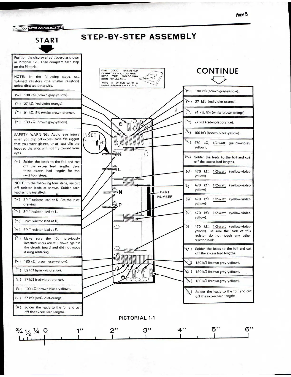
Position the display circuit board as shown
in Pictorial 1-1. Then complete each step
on the Pictorial.
NOTE:
In
the
following
steps,
use
1/4-watt
resistors
(the
smaller
resistors)
unless directed otherwise.
(\-)
180
kn (brown-
g
ray-yellow).
(‘--)
27 kfl (red-violet-orange).
1
91 Ica 5% (white-brown-orange).
N
Y 1
180 kS2 (brown-gray-yellow).
SAFETY WARNING: Avoid eye injury
when you clip off excess leads. We suggest
that you wear glasses, or at least clip the
leads so the ends will not fly toward your
eyes.
(s- 1
Solder the leads to the foil and cut
off
the
excess
lead
lengths.
Save
these
excess
lead
lengths for the
next four steps.
NOTE: In the following four steps, use cut
off resistor leads as shown. Solder each
lead as it is installed. lc
,
-
r
,
)
3/4" resistor lead at K. See the inset .
drawing.
N)
3/4" resistcr lead at L.
N)
3/4" resistor lead at
N.
'N
,
1
3/4" resistor lead at P.
(
)
Make
sure
the
fdur
previously
installed wires are still down against
the circuit board and did not move
during soldering.
(V)
180 kn (brown-gray-yellow).
(
L
)
82 kft (gray-red-orange).
t= )
27 ks
-
2 (red-violet-orange).
(k )
100 Id2 (brown-black-yellow).
(
1
27 ks2 (red-violet-orange).
(
1
/
44
)
Solder the leads to the foil and cut
off the excess lead lengths.
CONTINUE
''''t•.-)
180 Id2 (brown-gray-yellow).
*
1
°
1
27
Id2
(red-violet-orange).
*t.
(
)
91 kft, 5% (white-brown-orange).
("1
27 ks
-
2 (red-violet-orange).
(\ 1
100 Id2 (brown-black-yellow).
('''' )
470
kf2,
1/2-watt
(yellow-violet-
yellow).
NO
Solder the leads to the foil and cut
off the excess lead lengths.
1
-
J)
470
kft,
1/2-watt
(yellow-violet-
yellow).
AO
470
ka
1/2-watt
(yellow-violet-
yellow).
14:0
470
kfl,
1/2-watt
(yellow-violet-
yellow).
N)
470
162,
1/2-watt
(yellow-violet-
yellow).
ti )
470
kn,
1/2-watt
(yellow-violet-
yellow).
Be sure the leads of this
resistor
do
not
touch
any
other
resistor leads.
*
Nif 1
Solder the leads to the foil and cut
off the excess lead lengths.
\i,../1
180 kS2 (brown-gray-yellow).
\J., 1
180 kit (brown-gray-yellow).
)
180 ks2 (brown-gray-yellow).
‘
1\1
Solder the leads to the foil and cut
off the excess lead lengths.
PICTORIAL 1-1
FOR GOOD SOLDERED
CONNECTIONS. YOU MUST
KEEP THE SOLDERING
IRON TIP CLEAN
WIPE IT OFTEN WITH A
DAMP SPONGE OR CLOTH
.
PART
NUMBER
 Loading...