4-99 15 21322M
GC150 SERIES DIRECT VENT GAS APPLIANCE
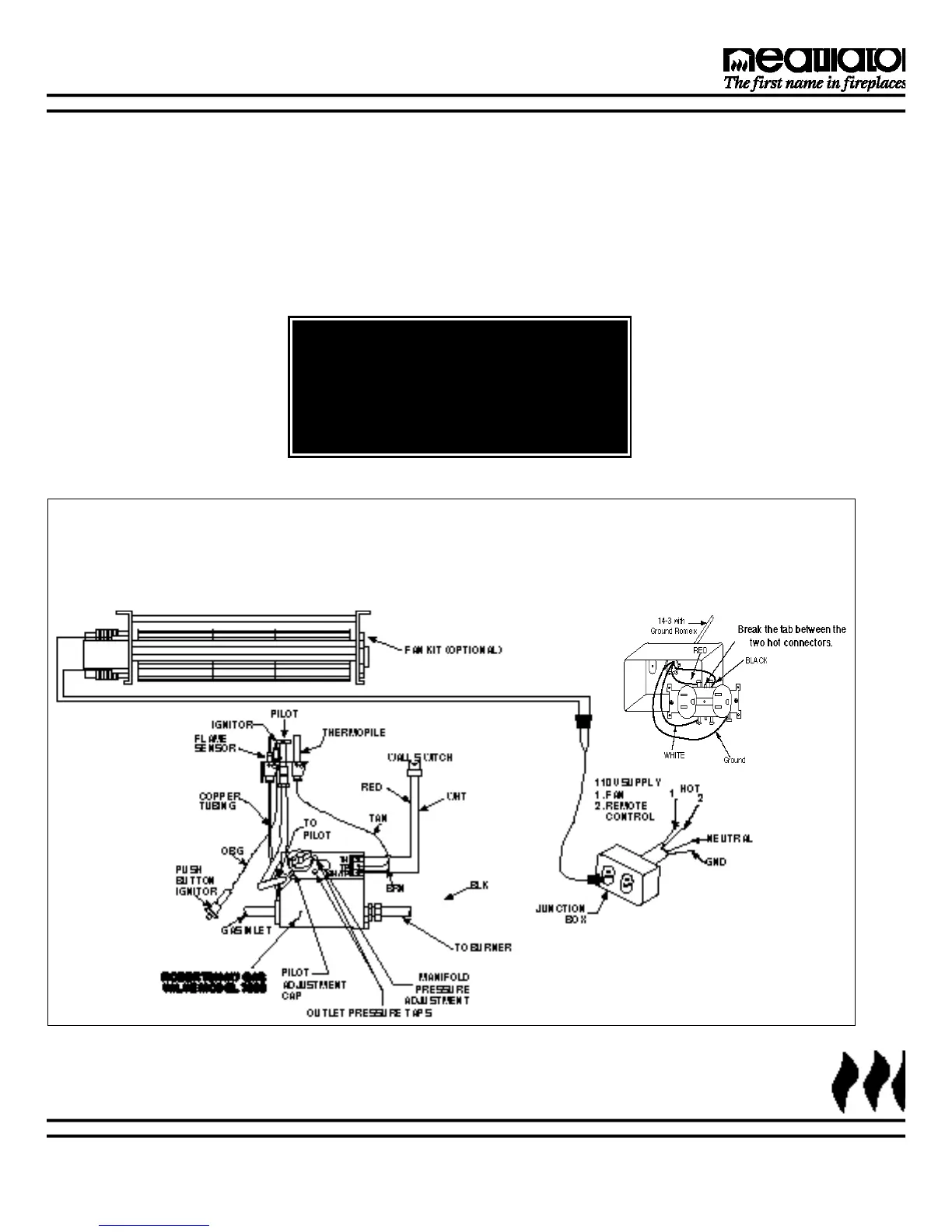
Figure 20
Standing Pilot Ignition Wiring Diagram
WA R N I N G !
This appliance DOES NOT require a
110VAC supply for operation. Connecting
the appliance/wall switch to a 110V AC
supply will cause the unit to malfunction
and destroy the valve and thermopile.
B. STANDING PILOT IGNITION
1. Appliance requirements. A wiring diagram is shown in
Figure 20.
2. Optional Accessories Requirements. Wiring for optional
accessories should be done now to avoid reconstruction.
14-3 with ground Romex is the recommended wiring to the appliance Junction
Box. This allows each outlet to power the unit and fan independently.
Detailed Picture of Junction Box