17 – 226 HEIDENHAIN Service Manual iTNC 530 HSCI
Control-is-ready
acknowledgement
The iTNC 530 HSCI receives information on the status of the EMERGENCY STOP chain trough the two
signals ES.A and ES.B (PLC inputs).
Both signals must be set. --> The EMERGENCY STOP chain is closed.
Axis-specific
drive enable
via axis groups
24 V must be available for the associated axis group at each of the PLC inputs defined by the machine
tool builder.
The axis-specific drive enable is defined in the following machine parameters:
MP4132 (PLC inputs for switch-off groups)
MP2040 (Assignment of the axes to the switch-off groups)
Drives ready
for operation
The drives must be ready for operation and report this condition.
With the HEIDENHAIN inverter system the green READY LEDs on the UM xxx drive modules or
on the output stages of a compact inverter/controller unit with integrated inverter must be lit.
When non-HEIDENHAIN inverter systems are used, the counterpart displays must be lit.
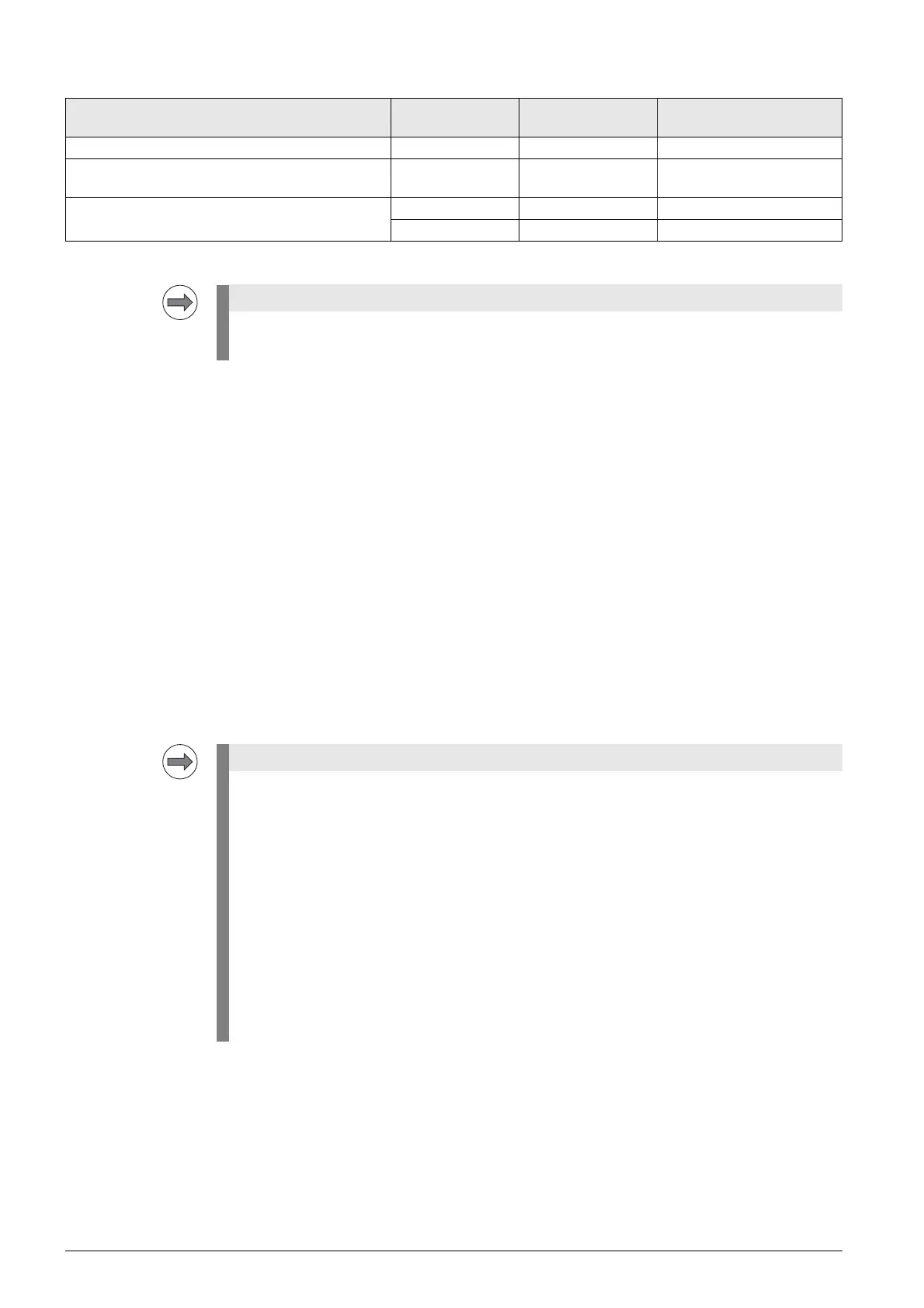
Integration of iTNC 530 HSCI into
EMERGENCY STOP chain
PLB 62xx UEC 11x Signal
Supply of "Control is ready" output X9, terminal 1a X4, terminal 1a - - -
"Control is ready" output X9, terminal 3a X6, terminal 12a MC.RDY or STO.A.G
(Safe Torque OFF)
"Acknowledgement of Control is ready" input X9, terminal 7a X5, terminal 9a ES.A (emergency stop A)
X9, terminal 7b X5, terminal 10a ES.B (emergency stop B)
Either the "Control is ready" output and input on the PLB 62xx system module or on
the UEC 11x compact controller unit are used.
When a drive is added to the control loop, the READY signal of the power output stage must
be transmitted to the control via the PWM cable within a defined period. For this purpose the
corresponding relays must have switched.
The iTNC monitors the time between the activation of the control loop and the READY signal
of the power output stages.
If the READY signal is missing after the waiting time has passed, the error message
8B40 No drive release <axis> appears.
A connection may be interrupted (wiring in the electrical cabinet, PWM cable between CC and
UM), the relays may switch too slowly or the drive be defective.
The permissible waiting time is entered in MP2170.
This error message may not be generated, as the PLC program does not hook up the current and
speed controllers as long as the ready signal of the drives is missing.
--> Watch the green READY LEDs of the drives.
--> See ”Readiness of the inverter system” on page 17 – 233.

 Loading...


