27 – 506 HEIDENHAIN Service Manual iTNC 530
X23:
Connection to
MC 42x (B/C)
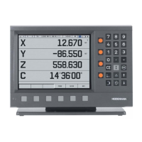
Pin layout on the HRA 110:
X31:
HRA 110 supply
voltage
Pin layout on the HRA 110:
Maximum current consumption 200 mA.
HRA 110
D-sub connection (female) 9-pin Pin layout
1RTS
20 V
3CTS
4 +12 V +0.6 V (U
V
)
5 Do not assign
6DSR
7RxD
8TxD
9DTR
Housing External shield
The power supply of the PLC must not be used simultaneously for the HRA110, otherwise
the metallic isolation of the PLC inputs/outputs would be bridged.
HRA 110
Connecting terminal Pin layout
1 + 24 Vdc as per IEC 742 (VDE 551)
20 V

 Loading...


