Do you have a question about the HEIDENHAIN TNC 135 B and is the answer not in the manual?
Details the available TNC 135 control versions (B, RT).
Essential operational guidelines and safety precautions for the TNC control.
Explains the purpose and layout of coding switches for configuration.
Lists four basic software versions for different operating modes.
Details software for drives with backlash and backlash-free configurations.
Introduces linear interpolation, Kv-adjustment, and related procedures.
Covers external voltage, buttons, feedback, limit switches, and E-Stop inputs.
Details relay output specifications, E-Stop, spindle lock, and mode outputs.
Details M, T, and S functions, their programming, and outputs.
Lists and describes the predefined fixed program cycles.
Explains V.24 connectivity, baud rate, and data transfer procedures.
Covers transducer code switches and compatible encoders for TNC 135.
Outlines essential checks before powering up the control unit.
Covers grounding, interface cabinet checks, and TNC setup.
Details the process of initial TNC setup and parameter programming.
Discusses batteries, transducer/traversing direction checks.
Covers adjustments for ramp length, offset, and trailing error.
Provides a detailed step-by-step checklist for initial setup.
Summarizes key technical features, speed, memory, and display.
Lists common operating errors and malfunctions for components.
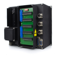
Shows connector layouts for TNC 135 B and TNC 135 RT models.
Illustrates terminal clamp assignments for various connectors (J1-J5).
Provides dimensional drawings and specifications for control units.
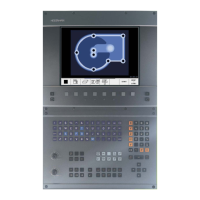
Shows the dimensions and layout of the BE 135 visual display unit.
Illustrates the adapter cable and its specifications.
| Control Type | CNC |
|---|---|
| Input Method | Keyboard |
| Number of Axes | 3 |
| Category | Industrial Equipment |
| Communication Interface | Serial interface (RS-232) |