Do you have a question about the HEIDENHAIN UV 105 and is the answer not in the manual?
Specialist execution required, follow safety regulations. Engage/disengage connections only when free of potential.
Comparison of connectors, connections, and availability between UV 105 and UV 101/UV 101B models.
Confirms full compatibility regarding electrical specifications between UV 105 and UV 101/UV 101B.
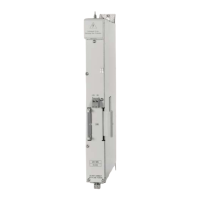
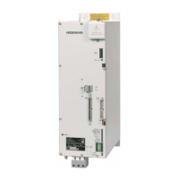
Diagrams showing front and bottom views of UV 101/UV 101B and UV 105 connectors and terminals.
Switch off, discharge, ensure no potential, and remove covers before starting installation.
Instructions for removing the old unit and installing the new UV 105 unit in the gap.
Details on connecting supply bus, grounding, and dc-link terminals as per new unit requirements.
Checks required according to DIN VDE 0113, part 1 / EN 60204-1 after component exchange.
Verify correspondence to documentation, grounding continuity, and perform a functional test.
Note to file replacing instructions and record changes in the machine's technical documentation.
Specialist execution required, follow safety regulations. Engage/disengage connections only when free of potential.
Variant 14 compatibility with reservations in mounting dimensions and ribbon cable length considerations.
Confirms full electrical compatibility between Variant 14 and variants 01, 02, 12, and 13.
Diagrams showing front and bottom views of UV 105 ID 344980-14 connectors and terminals.
Switch off, discharge, ensure no potential, and remove covers before starting installation.
Instructions for removing the old UV 105 unit and installing the new UV 105 unit.
Reestablish connections and use extension cable if ribbon cable length is insufficient.
Checks required according to DIN VDE 0113, part 1 / EN 60204-1 after component exchange.
Verify correspondence to documentation, grounding continuity, and perform a functional test.
Note to file replacing instructions and record changes in the machine's technical documentation.
| Input Voltage | 100-240 V AC |
|---|---|
| Protection Class | IP20 |
| Output Voltage | 5 V DC |
| Operating Temperature | 0 °C to 50 °C |
| Storage Temperature | -20 °C to 70 °C |