Do you have a question about the Heiko Thermal 6 and is the answer not in the manual?
General safety precautions and warnings for using the heat pump system.
Detailed safety guidelines and specific warnings related to electrical and operational safety.
Explanation of how the DC inverter air to water heat pump system operates.
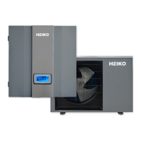
Identification and overview of the key components of the indoor and monoblock units.
Technical specifications and performance data for the heat pump models.
Diagram illustrating the decision process for selecting the correct system configuration.
Wiring diagram for a specific assembly configuration (One Temperature Zone, without DHW).
Wiring diagram for another assembly configuration (One Temperature Zone, with heating-only).
Wiring diagram for a third assembly configuration (Two Temperature Zones, without DHW).
Wiring diagram for a fourth assembly configuration (Two Temperature Zones, with heating-only).
Wiring diagram for a fifth assembly configuration (Two Temperature Zones, with heating-only).
Wiring diagram for a sixth assembly configuration (One Temperature Zone, with DHW).
Wiring diagram for a seventh assembly configuration (One Temperature Zone, with heating-only).
Wiring diagram for an eighth assembly configuration (Two Temperature Zones, with DHW).
Wiring diagram for a ninth assembly configuration (Two Temperature Zones, with heating-only).
Wiring diagram for a tenth assembly configuration (Two Temperature Zones, with heating-only).
Overview of different system applications for sanitary hot water setup.
Guidelines for setting up heating and cooling distribution systems, including buffer tank requirements.
Configuration options for controlling heating and cooling circuits.
Detailed settings for Heating/Cooling Circuit 1, including temperature control.
Detailed settings for Heating/Cooling Circuit 2, including temperature control.
List of essential tools required for the installation process.
Step-by-step instructions for mounting and installing the indoor control unit.
Instructions for installing the monoblock outdoor unit, including placement and clearance.
List of included accessories and their quantities for the heat pump system.
Detailed explanation of terminal blocks and wiring connections for the system.
Procedure for installing the safety valve kit onto the indoor control unit.
Instructions for connecting water pipes, including filtration and insulation requirements.
Steps for performing a pre-start up check and initial system test run.
Overview of the operation panel interface, including symbols, modes, and warnings.
Detailed settings and operational guidance for Heating/Cooling Circuit 1.
Detailed settings and operational guidance for Heating/Cooling Circuit 2.
Configuration settings for Domestic Hot Water (DHW) operation, including timers and priority.
Setting a reduced temperature for heating during specific periods for energy saving.
Activating and configuring the anti-legionella function to prevent bacterial growth.
Using vacation mode to reduce energy consumption during unoccupied periods.
Managing user permissions and system settings for the heat pump.
Selecting and configuring operating modes like Sanitary Hot Water, Heating, and Cooling.
Configuring auxiliary heating sources like AH, HBH, and HWTBH for system support.
Adjusting circulation pump settings for heating and cooling operations.
Procedure for floor curing operation in newly installed heating systems.
Utilizing the electrical utility lock for energy saving during peak demand periods.
Configuring other system options like motorized diverting valve and control panel backlight.
Viewing real-time operational data and system parameters for monitoring.
Information on the operation and control of the electric heater.
List of error codes, their descriptions, and solutions for troubleshooting.
Safety precautions to be observed during maintenance of units with flammable refrigerants.
Important notes and considerations regarding system maintenance and operation.
Instructions for cleaning the water filter to ensure proper system performance.
Procedure for cleaning the plate heat exchanger for optimal efficiency.
Guidelines and requirements for charging refrigerant into the system.
Maintenance and cleaning procedures for the condenser coil.
Steps for servicing and maintaining the indoor control unit's electrical components.
Maintenance and service procedures for the monoblock outdoor unit components.
Dimensional drawings and outlines of the indoor control unit and monoblock units.
Exploded views of the indoor control unit and monoblock unit components.
Wiring diagrams for the indoor control unit.
Wiring diagrams for the monoblock unit.
Detailed wiring connections for water mixing valves and PCBs.