Do you have a question about the HEKA Elektronik EPC 10 USB and is the answer not in the manual?
Provides an overview of the EPC 10 USB amplifier, its features, and capabilities.
Lists cited articles and books relevant to patch clamp techniques and the EPC 10 USB.
Explains the naming conventions used for amplifier types and operating systems in the manual.
Details the headstage component and available exchangeable headstages for the EPC 10 USB.
Describes the standard Red Star Headstage, its connectors, and important notes for handling.
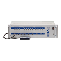
Covers the main amplifier unit, including front-panel and rear-panel connectors and controls.
Explains the multi-amplifier versions of the EPC 10 USB and their DA/AD channel configurations.
Highlights unique features of the EPC 10 USB, such as the double staggered acquisition timing.
Outlines the steps for installing only the software, requiring a protection key and software installation.
Details the four steps for installing both the hardware and software, including connections and calibration.
Defines conventions used for software, hardware, and operating system versions throughout the manual.
Provides instructions on connecting the EPC 10 USB hardware to a computer and power supply.
Explains the necessity and procedure for installing the software protection key (dongle).
Guides the user through the process of installing the control software on MS Windows and MacOS.
Describes the procedure for calibrating the amplifier, its importance, and steps involved.
Provides contact information and details required for contacting HEKA support for assistance.
Guides users through testing amplifier functions using a provided model circuit.
Describes the Full Test feature in PATCHMASTER for diagnosing hardware problems.
Explains the main amplifier window in PATCHMASTER and its controls for amplifier setup.
Details rarely used controls accessible by resizing the window or using the 'Show All' tab.
Covers the EPC 10 USB menu options, including Test and Calibrate functions.
Explains the fundamental Voltage Clamp mode of the EPC 10 USB amplifier.
Describes the Current Clamp mode for measuring resting potential and action potentials.
Details a modified current clamp mode for measuring potential deflections at constant average potential.
Explains the software emulation of the traditional search mode for adjusting zero-current potential.
Explains series resistance compensation, its effects, and the EPC 10 USB's circuitry for it.
Describes automatic procedures for fast (C-fast) and slow (C-slow) capacitance subtraction.
Details handling amplifier, electrode, and liquid junction offsets using Vo, Auto-Vo, and LJ features.
Provides guidelines for attaching the pipette holder to the probe for low noise recording.
Advises on running separate ground wires to minimize magnetic pickup and ground loop effects.
Emphasizes grounding the microscope and its components for proper shielding.
Discusses the use of Faraday cages and screens for electrostatic shielding against line-frequency pickup.
Suggests connecting an oscilloscope and other instruments to the EPC 10 USB for monitoring.
Details the importance of shielded vs. unshielded holders and pipette preparation.
Describes the requirements for a stable bath electrode and provides an illustration.
Lists sources and types of glass capillaries used for pipette fabrication.
Explains the two-stage process of pulling glass pipettes to create the desired tip diameter.
Describes pipette coating with Sylgard to reduce capacitance and noise.
Explains heat polishing for smoothing pipette tips and removing contaminants.
Provides guidance on handling and filling pipettes to ensure optimal performance.
Details the initial setup and process of forming a seal between the pipette and the cell membrane.
Explains how to perform cell-attached recording after forming a seal.
Guides through the process of breaking the patch to achieve whole-cell configuration.
Describes switching to and using the current clamp recording mode.
Discusses minimizing noise sources and optimizing the setup for low noise measurements.
Details the pin assignment and purpose of the 40-pin Digital I/O connector.
Describes the Digital In connector (DSub-25, female) for TTL trigger signals.
Describes the Digital Out connector (DSub-25, female) for triggering external devices.
Mentions an optional breakout cable for accessing digital outputs/inputs via BNC connectors.
Lists available connecting cables for integrating with other HEKA devices or peripherals.
Describes the standard mounting plate for connecting the pre-amplifier to micromanipulators.
Details the dovetail adapter for connecting to specific micromanipulator models.
Introduces the S-Probe, highlighting its reduced size, weight, and optional bath sense connection.
Describes BNC-type pipette holders compatible with the Red Star Headstage.
Describes SMA-type pipette holders compatible with the S-Probe.
| Brand | HEKA Elektronik |
|---|---|
| Model | EPC 10 USB |
| Category | Amplifier |
| Language | English |