16
Fresh Air Boxes
Installation and Operating Instructions
6.4.2 Connection of main unit and extract air unit
If an extract air unit is installed in addition to the main unit, both will be controlled by a joint control unit which is installed
on the main unit. The control units of both units are connected with a data cable.
- Connect data cable to the connector of the circuit board of the extract air unit.
- Connect the other end of the control line to any RJ socket of the circuit board of the main unit.
The power cables are separately connected to each unit.
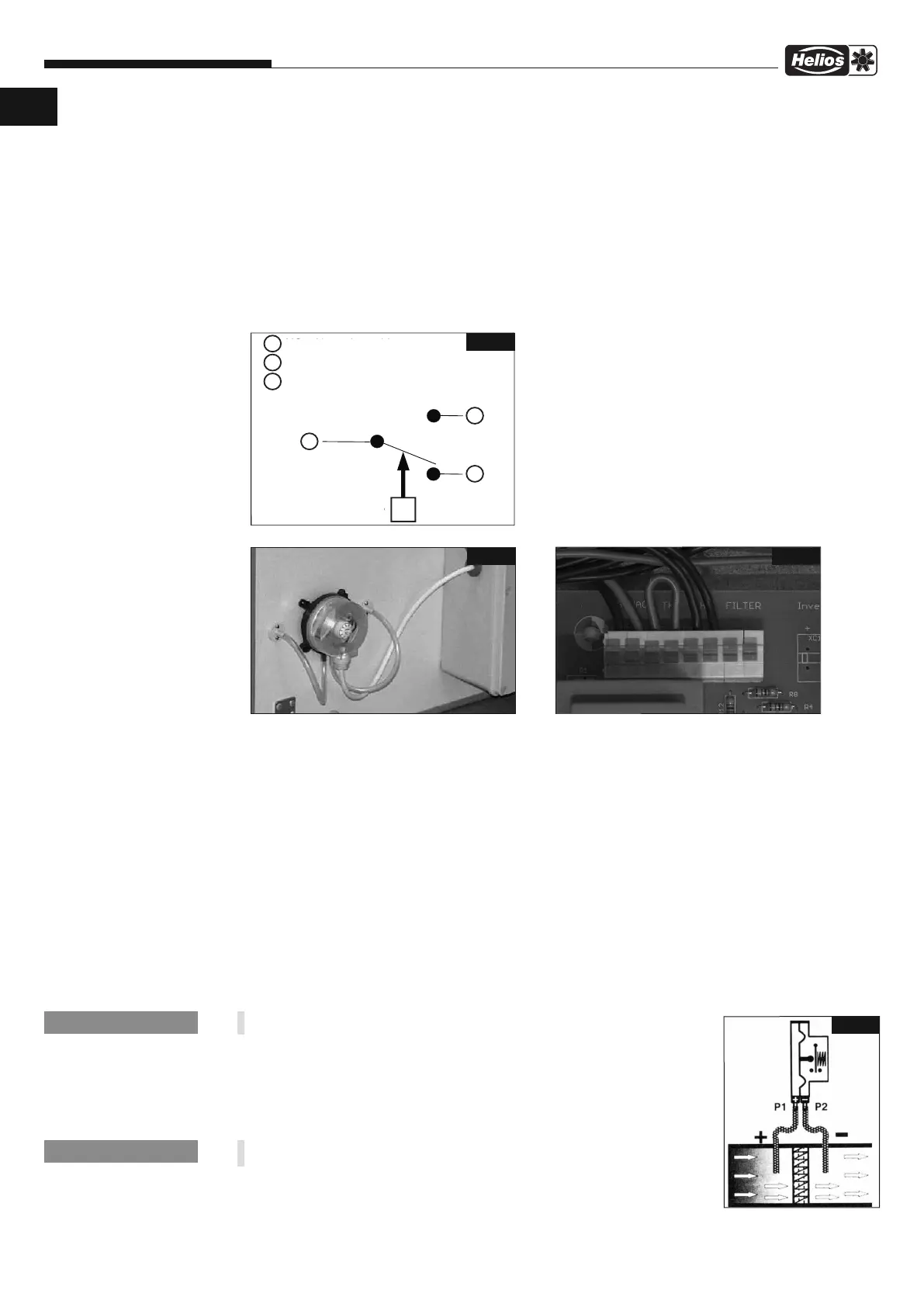
6.4.3 Connection: Differential pressure switch DDS for filter monitoring (Accessories, Ref.no.: 0445 )
Specification
Electrical load: Max. 1.5A (0.4 A) / 250 VAC
Electrical protection class: IP 54 with closed cover.
Recommended cable diameter 6 mm.
Connection in the differential pressure switch
Wiring diagram for differential pressure switch DDS.
(See also wiring diagrams SS-1121 to SS-1126, Pt 1).
Switching functions:
While differential pressure is increasing:
1 opens
2 closes
While differential pressure is decreasing:
1 closes
2 opens
Installation position of DDS Connection in terminal box on control board
Installation of the DDS
1. Check the contents of the packaging for completeness.
2. There are corresponding drill holes in the casing for the installation. Drill two Ø 7 mm holes Ø 7 mm holes in the
external drill holes.
3. Insert the bushings into the drilled holes and fix them by screwing.
4. Unscrew casing of differential pressure switch.
5. Loosen fixing screw and remove front cover.
6. Cut the rubber hose in two pieces. Connect the rubber tubes from the differential pressure switch to the
bushings in the casing:
- Connect the rubber tube from bushing 1 (before the filter) to the dark grey supply line 1 from the differential pres
sure switch (Fig. 9).
- Connect the rubber tube from bushing 2 to the supply line from the differential pressure switch (Fig. 9).
7. Insert the delivered cable into the DDS with fasteners inside and connect them to the contacts 1 and 3.
8. Set the pressure by rotating knob (with new filter) ± until the filter signal responds. Afterwards, set it to 2 ti-
mes the switching value (fan speed stage 5.
The filter monitoring is active from fan speed stage 2.
9. Close the DDS with the front cover and tighten the screw.
10. Insert the connection cable through the side opening in the terminal box.
Connect the cable to the terminal box pursuant to wiring diagrams SS-1121 to
SS-1124, Pt 1.
In direction of the volume flow connection P1 (+) is connected before and
connection P2 (-) after the in the air duct (Fig.11)
1
NC
=
Nor
m
al
gesch
l
osse
n
NO
=
n
or
m
al
geöf
f
n
e
t
COM
=
gem
e
i
n
sam
er
An
sch
l
u
ss
C
O
M
N
O
Schal
t
kont
akt
-
P
3
2
N
C
1
P
3
2
+
-
F
i
g
.8
F
ig
.9
F
ig
.10
Fig.11
NOTE
☞
NOTE
☞
UK
+
-
NC Normal closed
NO Normal opened
COM Common connection
Switching contact
 Loading...