EN
EN
Fan casing types ELS-GAP / ELS-GAPB
Installation and Operating Instructions
4
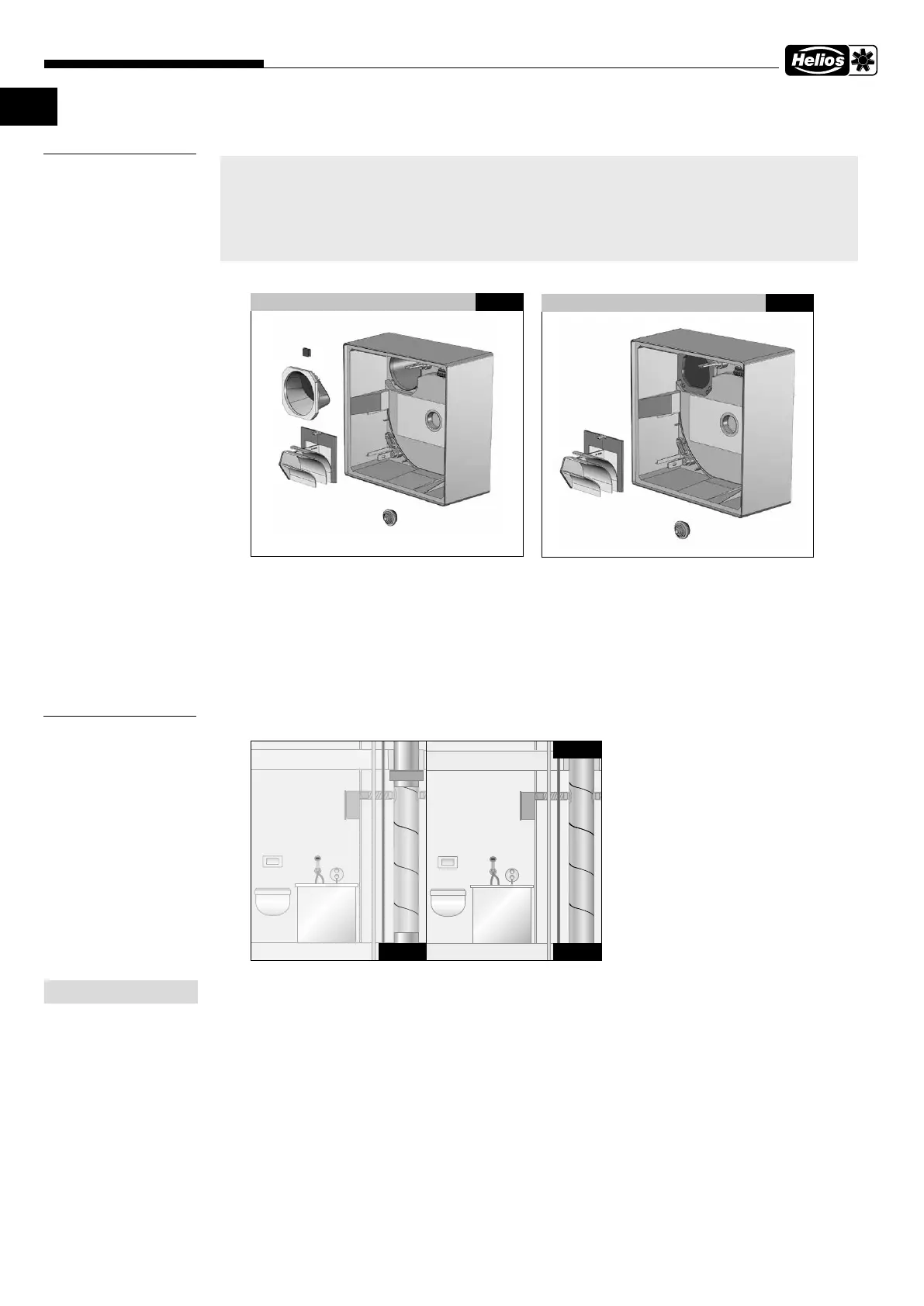
3.1 Scope of delivery / packaging unit, Fig.1-2
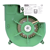
ò Surface-mounted casing ELS-GAP with electrical plug connection
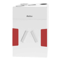
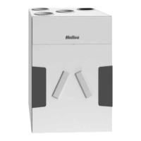
ù Surface-mounted casing ELS-GAPB with fire protection shutter and with electrical plug connection
ä Metal discharge openings with automatic check valve and shut-o in case of fusible link triggering
ë Cable grommet
ö
ELS-ARS reversion kit, rear discharge, keep in casing until final assembly,
spiral insert only required for final assembly
ü Valve casing with air-tight backdraught shutter
Å Balancing weight
4.0 Installation location / position
If the ELS casings are used in highly resonant lining boards (e.g. chipboard, gypsum or fibre silicate boards),
then the transmission of structure-borne sound must be prevented with elastic spacers.
A distance of 20 cm from the ELS casing to the wall and ceiling is recommended for the side inflow.
3.0 ELS-GAP plastic casing without fire protection
– suitable for installation in buildings without fire protection requirements pursuant to LBO (regional building code).
– suitable for installation in buildings with fire protection requirements pursuant to LBO in conjunction with the ins-
tallation of fire damper ELS-D.
ELS-GAPB with fire protection shutter K90
– suitable for installation in buildings with fire protection requirements K90.
CHAPTER 3
ELS SCOPE OF DELIVERY
A
ND ASSEMBLY
Fig.1
ë
ö
ü
ELS-GAP Surface-mounted casing
ò
Å
Fig.2
ë
ö
ELS-GAPB Surface-mounted casing
ù
¬
ä
CHAPTER 4
INSTALLATION
ELS
WC
GAP GAPB
ELS
WC
Fig.3
NOTE
+