18
normally does not contain any information
DERXWWKHYROXPHOHYHO.HHSLQPLQGWKDWWKLV
ZLOOOHDGWRIXOOOHYHORQWKHRXWSXWVRIWKH+(/,;
'63DQG\RXUFRQQHFWHGDPSOL¿HUV7KLVPD\
FDXVH VHYHUH GDPDJH WR \RXU VSHDNHUV :H
strongly recommend to use an optional remote
FRQWUROIRUDGMXVWLQJWKHYROXPHOHYHORIWKHGLJ-
ital signal input!
Information: The HELIX DSP.2 can only han-
dle uncompressed digital stereo signals in PCM
format with a sample rate between 12 kHz and
96 kHz and no Dolby-coded signals.
5. Connection to power supply
Make sure to disconnect the battery before
installing the HELIX DSP.2!
Solely use the included screw-type terminal
to connect the HELIX DSP.2 to a power sup-
ply. Make sure of correct polarity. The ground
ZLUHPXVWEHFRQQHFWHGWRWKHYHKLFOHFKDVVLV
at a non-insulated point. Inadequate grounding
causes audible interference and malfunctions.
7KH SRVLWLYH ZLUH KDV WR EH FRQQHFWHG WR WKH
EDWWHU\¶V SRVLWLYH SRVW RU D SRZHU GLVWULEXWLRQ
block. Though the current draw of the HELIX
'63 LV UDWKHU ORZ DSSUR[ P$ ZH UHF-
RPPHQG D PLQLPXP ZLUH JDXJH RI PPð
AWG18 for both power supply wires.
6. Connecting the remote input
The remote input of the Power Input has to be
connected to the radio remote output if the sig-
QDOSURFHVVRUVSUHDPSOL¿HULQSXWVRUWKHOpti-
cal Input are solely used as signal inputs. We
do not recommend controlling the remote input
YLDWKHLJQLWLRQVZLWFKWRDYRLGSRSQRLVHGXULQJ
turn on/off. If the Highlevel Input is used this in-
put does not need to be connected as long as
the car radio has BTL output stages.
&RQ¿JXUDWLRQRIWKHUHPRWHLQSXW
The DSP.2 will be turned on automatically if the
Highlevel Input is used or if a signal is applied
to the remote input terminal. The “Auto Remote”
VZLWFKDOORZVWRGHDFWLYDWHWKHDXWRPDWLFWXUQ
RQIHDWXUH7KHIHDWXUHVKRXOGEHGHDFWLYDWHGLI
there are e.g. noises while switching on/off the
signal processor.
Note: If the automatic turn-on function is deac-
WLYDWHGLWLVPDQGDWRU\WRXVHWKHUHPRWHLQSXW
terminal to power up the signal processor! The
KLJKOHYHOVLJQDOZLOOEHLJQRUHGLQWKLVFDVH
Note:7KHDFWLYDWLRQRIWKHVLJQDOSURFHVVRUYLD
VSHDNHULQSXWLVDFWLYDWHGH[ZRUNV
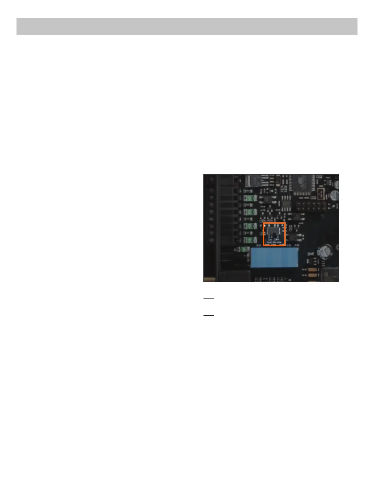
7R GHDFWLYDWH WKH DXWRPDWLF WXUQRQ IHDWXUH
\RX KDYH WR RSHQ WKH GHYLFH DQG FKDQJH WKH
position of the “Auto Remote” switch. Therefore
dismantle the side panel (where the USB input
LV ORFDWHG E\ UHPRYLQJ WKH ¿YH VFUHZV IRXU
Phillips screws and one allen screw). Now you
can pull out the bottom plate and get access to
the switch. The switch is located near by the
KLJKOHYHO VSHDNHU LQSXWV VHH PDUNLQJ LQ WKH
following picture).
On: $FWLYDWLRQ YLD KLJKOHYHO VSHDNHU LQSXW LV
HQDEOHGH[ZRUNV
Off: $FWLYDWLRQ YLD KLJKOHYHO VSHDNHU LQSXW LV
disabled.
&RQ¿JXUDWLRQRIWKH'63
The general DSP settings should be con-
ducted with the DSP PC-Tool software be-
IRUHXVLQJWKHVLJQDOSURFHVVRUIRUWKH¿UVW
time.
,JQRULQJWKLVDGYLFHPD\UHVXOWLQGDPDJLQJWKH
FRQQHFWHGDPSOL¿HUVWKHORXGVSHDNHUV,QIRU-
mation about connecting the DSP.2 to a com-
puter can be found on page 21.
9. Connecting the remote output
This output (Remote out) is used to supply re-
PRWHVLJQDOVWRWKHH[WHUQDODPSOL¿HUV$OZD\V
use this remote output signal to turn on the am-
SOL¿HUVLQRUGHUWRDYRLGRQRIIVZLWFKLQJQRLVHV
Installation
 Loading...