11
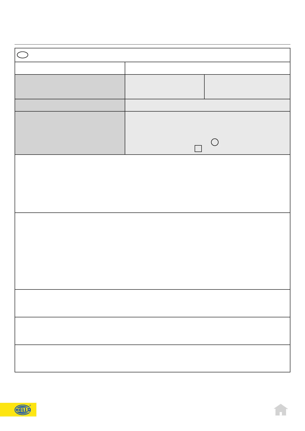
Technical data
General Technical Data BSN-LED Blue
Rated voltage:
Operating voltage:
Mean power consumption:
12 V
9 V to 32 V
800 mA
24 V
9 V to 32 V
400 mA
Dimensions: 151 mm x 58 mm x 26.6 mm
Cable length:
Protection category:
Temperature range:
Storage temperature:
Type test light - blue:
Type test EMC:
300 mm
IP5K4K, IP9K
-40 °C to +60 °C
-40 °C to +85 °C
ECE R65 XB1 E1 002796
e1 035615
Instructions for reprogramming ashing sequence
Connect programming lead (yellow) to + (power supply)1.
BSN-LEDexitsfromashingmode,afterapprox.2sthelampashesforapprox.1s2.
Flashing sequence (1) is selected if the yellow lead is now disconnected from the 3.
power supply
Iftheprogrammingleadremainsconnectedtothepowersupply,theelectroniccontrolselectsaftereachashing4.
cyclethenexthigherashingsequence.Ifthenalashingsequencehasbeenreached,programmingmodeisauto-
matically terminated.
Stored ashing sequences
P1 Singleash—SynchronisationECE-conform
P2 Doubleash—SynchronisationECE-conform
P3 Tripleash—Synchronisation
P4 Quadrupleash—Synchronisation
P5 Singleash—Alternating
P6 Doubleash—Alternating
P7 Tripleash—Alternating
P8 Quadrupleash—Alternating
P9 Permanent light with 50% brightness level
P10 Hella random flashing sequence. Flashing sequences alternate between 1-flash
➞
4-flash
Synchronization of two, three or four BSN-LED – Circuit diagram A
Connect synchronization leads (yellow) together1.
Flashingsequences1-4canbesynchronizedtothesameashingsequence2.
Alternating operation of two BSN-LED
Program one lamp to program location 1 - 4 and the other to program location 5 - 81.
Connect the synchronization leads (yellow) together2.
Permanent light dimmed – Circuit diagram B
Ifthesynchronouscable(yellow)isswitchedtogroundviaa6.8kΏresistor(seecircuitdiagramB),thelampworksin
permanent light mode with only 10% of the max. brightness. This circuitry is not permitted within the context of ECE.
EN
EN
 Loading...