Do you have a question about the Hella TC-400 and is the answer not in the manual?
Disconnect the negative battery terminal before working on the car's electrical system.
Avoid sharp edges to prevent damage to the wire harness and antenna.
Ensure the wiring harness and antenna are routed and fixed correctly.
Install all parts according to the provided illustrations.
Refer to the vehicle workshop manual for part disassembly/assembly.
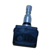
Four wheel sensors are included in the kit for monitoring tire pressure.
The central receiver module for the Tire Pressure Monitoring System.
The flexible antenna for receiving signals from the sensors.
The display unit for showing tire status and alerts.
Includes screws, power harness with fuse, cable ties, and connectors.
Includes display mounting bracket and double-sided tape pads.
The comprehensive manual for installation and operation.
Sensor location designation for the left front tire.
Sensor location designation for the right front tire.
Sensor location designation for the left rear tire.
Sensor location designation for the right rear tire.
Press and hold the Check button, then turn on the vehicle ignition.
Analyze bar indicators for receiver location suitability and interference levels.
Sensor positions are indicated on a label attached to the sensor body.
Follow the procedure to change wheel locations after tire rotation.
Procedure for (Re)Programming Wheel Locations after sensor replacement.
Press Check button, turn ignition on, release when 'Ln5' displays.
Deflate the spare tire to program its sensor.
Hold Check button for 3 seconds to skip spare wheel programming.
Deflate the left front tire to program its sensor.
Deflate the right front tire to program its sensor.
Deflate the right rear tire to program its sensor.
Deflate the left rear tire to program its sensor.
Procedure for programming extra sensors for 6-wheel vehicles.
Inflate all tires to the prescribed pressures as indicated on the vehicle.
Press and hold the Check button, then turn on the vehicle ignition.
Tire positions flash until all sensor data is received.
Display shows positions briefly before switching off.
System provides warnings for 25% and 50% pressure loss, respectively.
Default settings are 25% for first stage and 50% for second stage alerts.
Press and hold the Check button for 6 seconds.
Adjust the first stage warning level between 60% and 90%.
Push the Check button for 3 seconds to confirm the setting.
Adjust the second stage warning level between 50% and 80%.
Push Check button for 3 seconds to confirm and exit setup.
System performs a self-check and receives updated wheel location information.
Press Check button to view the Left Front tire's condition.
Press Check button to view the Right Front tire's condition.
Press Check button to view the Right Rear tire's condition.
Press Check button to view the Left Rear tire's condition.
Procedure for vehicles without a spare wheel.
Procedure for vehicles equipped with a spare wheel.
Procedure specific to vehicles with six wheels.
Press Check button to exit setup mode when using a spare wheel.
View condition of the left outer rear tire on 6-wheel vehicles.
View condition of the spare tire on 6-wheel vehicles.
Press Check button to exit setup for 6-wheel vehicles.
Indicates all tire conditions are OK.
First stage (orange) and second stage (red) low pressure alerts.
Alert for rapid pressure loss exceeding 3 PSI within one minute.
Alert for excessively high tire pressure levels.
Alert for tires operating at high temperatures (above 85°C or 185°F).
The system's buzzer activates for any alarm or alert condition.
Press the Check button to silence the buzzer temporarily.
An antenna icon indicates a lost sensor signal for over 10 minutes.
Address interference, sensor damage, or empty sensor battery.
Temporarily disable sensor or change tire positions on screen.
Press and hold the Check button for 5 seconds.
Locations light up sequentially during the spare tire change process.
Press Check button to confirm the spare tire replacement.
Press and hold Check button to restore original tire settings.
Shows sequential lighting of tire locations during the process.
Press Check button to accept the tire replacement.
Press and hold Check button for 5 seconds for defective sensor management.
Press Check button to temporarily disable a defective tire location.
Restore original settings for a defective location.
Press Check button to display a temporarily disabled location.
Press Check button to reinstate and activate a disabled location.
System uses default PSI and Fahrenheit settings.
Press and hold Check button, then turn on ignition.
Change pressure units to Kilopascals (kPa).
Change temperature units to Fahrenheit (°F).
Set pressure in kPa and temperature in Fahrenheit.
Set pressure in PSI and temperature in Celsius.
Set pressure in PSI and temperature in Fahrenheit.
Set pressure in Bar and temperature in Celsius.
Press and hold Check button for 3 seconds to confirm.
Press Set button to display preset front and rear wheel pressures.
Press and hold the Set-up button for 3 seconds.
Use Set-up button to cycle through colors and confirm choice.
Select US (Yellow) or EU (Orange/Red) warning color strategies.
Press and hold Set-up button to choose between US or EU settings.
Monitors pressure/temp; does not perform actions or detect all defects.
Driver must verify system self-check after ignition.
No liability for incorrect installation, damage, or signal loss.
| Brand | Hella |
|---|---|
| Model | TC-400 |
| Category | Measuring Instruments |
| Language | English |