Do you have a question about the Hellenbrand Iron curtain System 2.0 and is the answer not in the manual?
System removes iron via aeration, precipitation, and multi-media filtration.
System removes manganese through aeration, precipitation, and multi-media filtration.
System removes hydrogen sulfide using aeration, precipitation, and multi-media filtration.
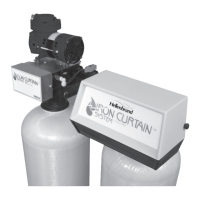
The first component of the Iron Curtain System, responsible for oxidation.
The second component, a multi-layered filter for removing precipitates.
Water is sprayed through air to convert dissolved elements into particles.
Allows contact time for dissolved elements to form filterable particles.
Utilizes a multi-media bed to trap precipitated particles.
Timer controls the air pump and drain ports for air recharge.
Original systems tested and validated by WQA under S-200 Standard.
System uses no chemicals or salt for water treatment.
Eliminates need for air injectors, venturis, or micronizers.
Influent water pH must be 7.0 or higher for effective iron oxidation.
System rated for max 10 ppm iron; higher levels may affect performance.
Presence of iron bacteria may limit system life and performance; requires control.
Rated for max 10 ppm H2S; levels vary with barometric pressure.
Limit 2.0 ppm; amounts over 2.0 ppm may prevent iron removal. pH > 8.5 optimal.
Tannins > 0.5 ppm void warranty; organics can hinder iron removal.
Chlorine residual should be limited to max 1.0 ppm, preferably 0.5 ppm or less.
TDS > 500 ppm may indicate potential interference with iron reduction.
Minimum 30 psi required for backwash; maximum 70 psi.
Must exceed backwash rate by minimum 30 psi for entire backwash cycle.
Continuous 110 volts required for controls and aeration pump.
Plumbing should be free from lime and iron build-up; replace if heavily affected.
Install tanks after pressure tank and as close as practical.
Minimum 3/4" or equal to connection size; avoid overhead lines if possible.
Install ahead of aeration tank in vertical upflow position with 6" water column.
Always provide for a bypass on the filter system, recommended for both tanks.
Filtered water usually for household lines; outside faucets often raw water.
Adhere to all state and local plumbing and electrical codes during installation.
Install the 1" check valve in an upflow position on the raw water supply.
Plumb filtered water fixtures, like kitchen faucets, with a downward direction.
Connect raw water supply to down-flow inlet of aeration tank. Install bypass valve.
Connect aeration tank outlet to filter tank inlet. Install bypass valve.
Run 3/8" drain connection from aeration head assembly to a drain.
Run 1/4" vent port tubing to a drain to prevent water damage.
Recommend 1" diameter pipe between aeration tank and filter tank.
Flush plumbing until water is clear and foreign material is removed.
Plug in, slowly open bypass inlet valve to fill tank and reach full pressure.
Open bypass valves and run water at a fixture until clear.
Do not backwash the Iron Curtain Filter for 24 hours after installation.
Factory pre-set to cycle air compressor every 24 hours; adjustable via wiring schematic.
To initiate manually, unplug and plug back in the power cord.
Factory preset to backwash every third day; adjust as needed.
More frequent backwash needed for higher iron, bacteria, H2S, or manganese.
System uses a special media allowing longer filter runs between backwashes.
Factory settings are recommended; adjust if backwashing more frequently is desired.
Lists models (IC-10, IC-12) and corresponding tank sizes (10"x54", 12"x52").
Provides max service flow rate (GPM) and backwash rate (GPM) for each model.
Details the physical dimensions (WxHxD) required for installation.
Shows the flow of water through the water softener, aeration tank, and filter tank.
Illustrates separation of filtered water for household use and unfiltered for hosebibs.
Describes the plastic elbow connection check valve and its part number.
Describes the original brass check valve and its part number.
Lists parts for the air pump, including motor, head, and valve components.
Lists parts for the control valve, aeration tank, and filter tank assemblies.
Details electrical cords, tubing, fittings, and check valves used in the system.
Diagram shows filtered and raw water flow paths and component connections.
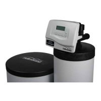
Lists various control valve options for IC-10 and IC-12 filter valves.
Wiring diagram for older models connecting air pump and solenoid valve to timer.
Wiring diagram for newer models with relay base and fixed air recharge time.
Table showing timer settings for various air recharge frequencies.
Diagram illustrating plumbing for the ProMate filter valve option.
Diagram illustrating plumbing for the WaterMate filter valve option.
Diagram illustrating plumbing for the AutoMate filter valve option.
Illustrates Normal, Bypass, Diagnostic, and Shut Off modes of the valve.
Lists parts and order numbers for the bypass assembly and its components.
Provides guidance on using hand tightening, Teflon tape, and avoiding pipe dope.
Details how water interacts with air in the aeration tank during service.
Explains how water flows through the multi-media filter bed.
Describes the process of the air pump recharging the aeration tank.
Explains timer control, solenoid valve, and shuttle valve functions.
Details how water flow reverses to clean the filter bed and discharge to drain.
Explains how water flow packs the clean filter bed and discharges to drain.
Lists components of the pump motor, head, and related fittings.
Details parts for the valve plate, piston sleeve, and valve flappers.
Lists parts for the pump housing, end cap, and front cover.
Instructions on removing the pump head, valve plate, and associated parts.
Guidance on removing and replacing piston sleeve and connecting rod.
Steps for replacing valve flappers, keeper strips, and O-rings.
Instructions for installing the front cover gasket and cover.
Addresses inadequate backwash, fouled media, and insufficient water supply.
Discusses causes like inadequate aeration or faulty pump.
Addresses issues where levels exceed manufacturer limits.
Covers loss of air via check valve or leaks, and pump issues.
Addresses seal failures or shuttle valve stuck in open position.
Explains the natural phenomenon of air release from aerated water.
Covers plugged inlet, fouled media, or restricted piping.
Addresses issues with check valves, reduced pressure, or faulty installation.
Covers new filter saturation and air passing through during backwash.
Addresses inadequate drain line size or vibration.
Discusses control valve stuck in regeneration cycle due to electrical or timer issues.
Addresses unplugged pump, stuck shuttle valve, or fouled solenoid vent.
Discusses corrosive water conditions and low pH.
Explains tolerance in timer settings affecting pump start times.
Instructions for removing water to prevent freezing damage.
Steps for shifting control valve to backwash and fast rinse.
Procedures for setting the aeration tank bypass to shut off mode.
Includes plugging drain, allowing air discharge, and removing pressure relief plug.
Details the WS1 Bypass Vertical Adapter Assembly and its parts.
Shows various PVC and brass fitting assemblies for the bypass.
Lists warranty durations for control valve body, aeration body, tanks, and entire filter.
Details defects not covered, such as misuse, neglect, or unauthorized service.
Outlines exclusive remedies and disclaims implied warranties.
| Brand | Hellenbrand |
|---|---|
| Model | Iron curtain System 2.0 |
| Category | Water System |
| Language | English |