SENSOR
The sensor is placed on the centre line of the sauna heater in accordance with the measurements specified in Image 1. The
sensor is equipped with a 5m heat-proof (T 170°C) 4 x 0.25mm
2
cable, which can be extended with a regular low-current
wire (with a similar cross-section).
ELECTRICAL INSTALLATION
Only a qualified electrician should connect the sauna heater and the control centre to the electrical power network
in accordance with the current regulations. The necessary connection diagrams are available inside the sauna heater and
the control centre and at the end of the operating instructions. The sauna heater must be connected semi-permanently with
medium-duty, or stronger, rubber cable H07RN-F (60245 IEC 66), see Table 1.
NOTE:. Do not use PVC insulated connection cable, which is prone to thermal embrittlement.
The connection box must be splash-proof and it must have a draining device. The height of connection box measured from
the floor must not exceed 500mm. If connection or installation cables are mounted on or inside the sauna wall at the height
of over 1,000mm from the floor they must resist at least 170°C when loaded (e.g. SSJ).
Electrical devices installed over 1,000mm from the floor must be approved for use in ambient temperatures over 125°C (T
125 marking).
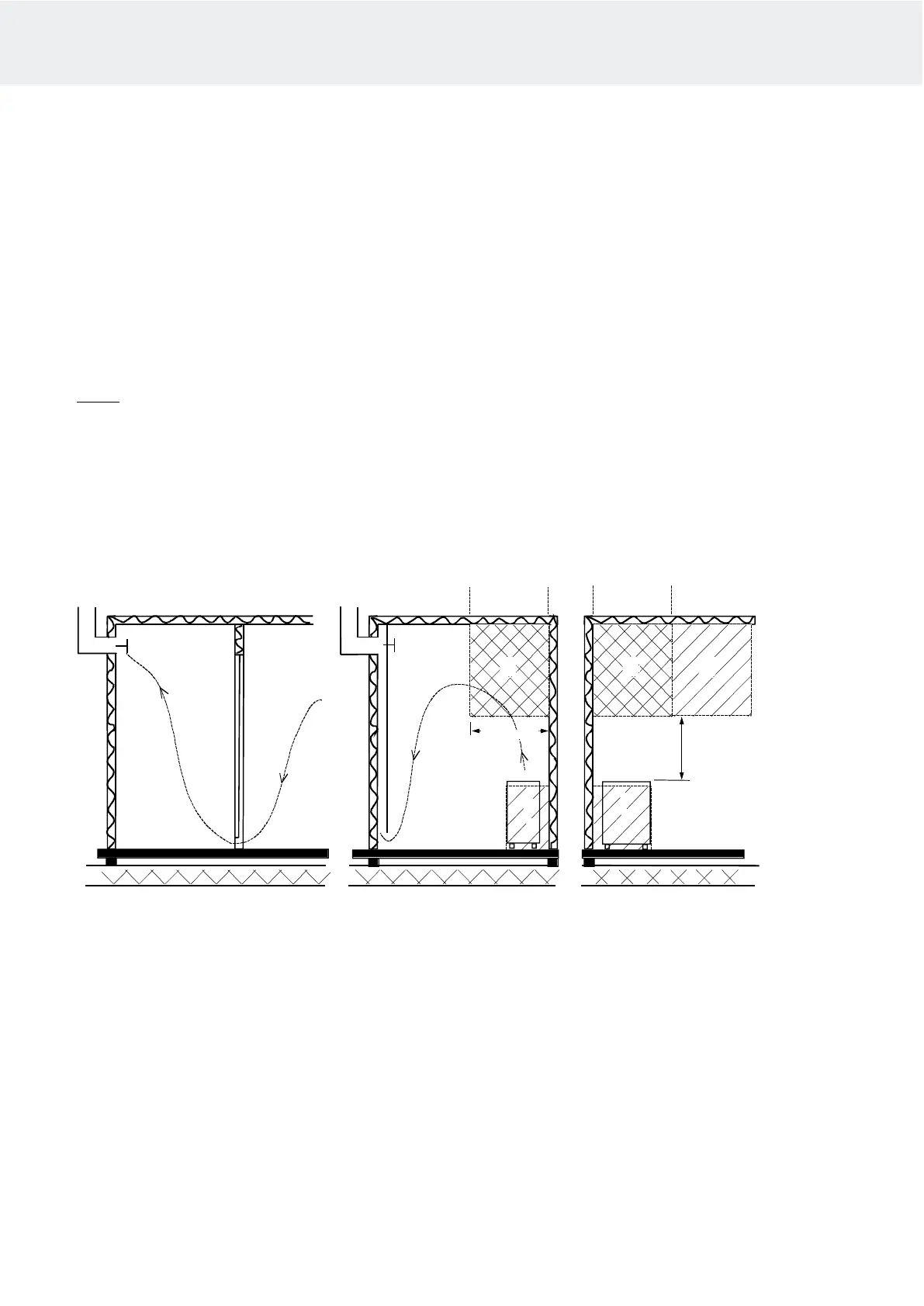
Recommended sauna room ventilation
1. Sauna room 3. Electric sauna heater 5. Exhaust flue or channel
2. Washroom 4. Exhaust valve 6. Door to the sauna room
7. A ventilation valve can be installed here to be kept closed while the sauna is heated and during bathing.
Inlet vent can be positioned in the A zone. Make sure the incoming fresh air will not interfere with (i.e. cool down) the sauna
heater's thermostat near the ceiling.
The B zone serves as the incoming air zone, if the sauna room isn't fitted with forced ventilation. In this case, the exhaust
valve is installed min 1m higher than the inlet valve.
DO NOT ISTALL INLET VALVE WITHIN ZONE C, IF THE SAUNA HEATER'S CONTROL THERMOSTAT IS LOCATED AT
THE SAME ZONE.
5
5
4
4
2
1
1
1
A
7
A
min
500 mm
6
3
B
3
B
C
C
C
C A
1000 mm
Instructions for use and installation LAAVA and SKLE
 Loading...