INSTALLATION AND OPERATING INSTRUCTIONS
72-0106 01-07-16 7013482 314 SKSM 215 A
Page 2
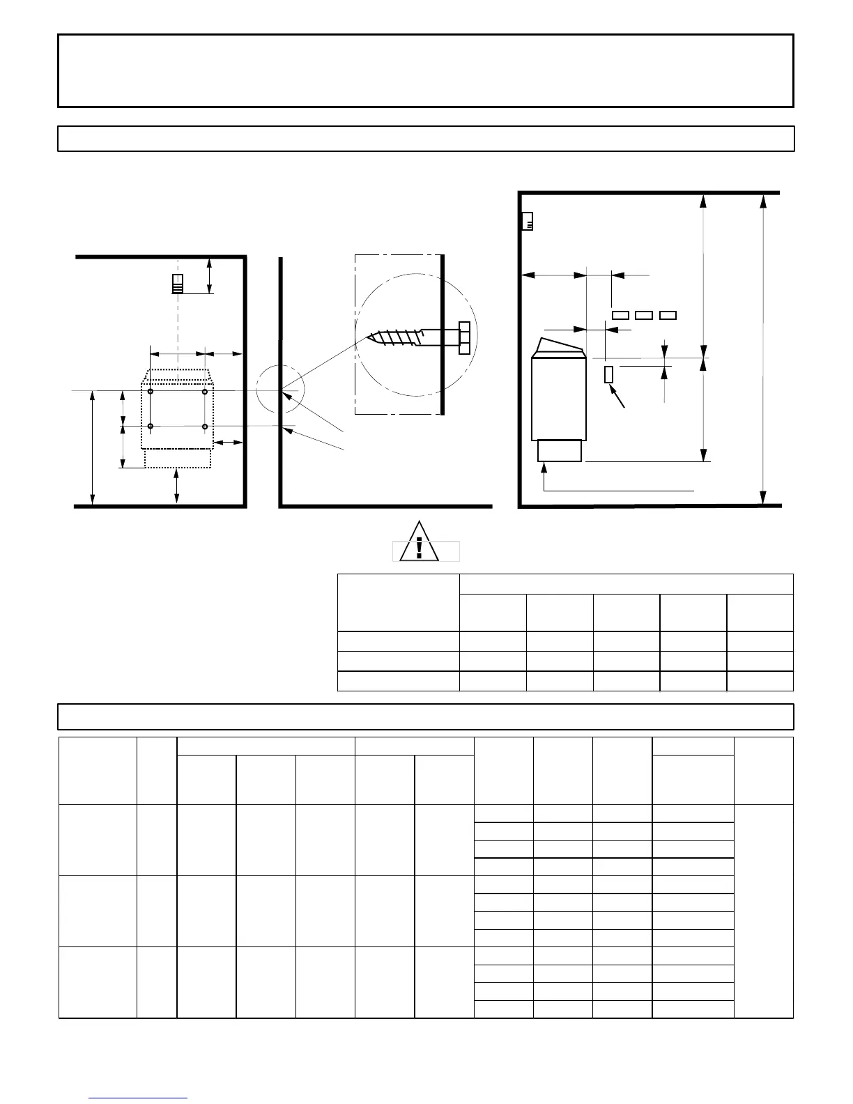
DIAGRAM 1
MOUNTING BRACKET LOCATION AND MINIMUM DISTANCE TO COMBUSTIBLE MATERIAL
C
High Limit Control
D
2"
1"
18½"
74"
Minimum
Screws
6"
14 3/8"
B
10½"
Use the long screws in the upper
holes of the mounting bracket
A
6½"
Min.
5"
Temperature
Sensor
44"
Minimum
Guard
Rail
(Upper Bench)
K
Recheck your distances from the heater to
combustible materials to be sure you have
the proper minimum distances.
NOTE 1: Use separate 120 volt branch circuit protected for 15 amps if control switch is to be used for lighting.
DIAGRAM 2
OBSERVING MINIMUM DISTANCES IS REQUIRED
TO REDUCE THE RISK OF FIRE
"A"
DISTANCE
"B"
DISTANCE
"C"
DISTANCE
"D"
DISTANCE
"K"
DISTANCE
Designer 4.5 3.0" 3 5/8" 4.0"
11 1/2"
23"
Designer 6.0
4.0" 4 5/8" 5.0" 11 1/2"
23"
Designer 8.0
5.0" 5 5/8" 6.0" 11 1/2"
23"
HEATER
MINIMUM
WIRE SIZE
Floor Area
Ceiling
Height
Volume
Cu.Ft.
Ceiling
Height
Volume
Cu.Ft.
Power Supply
to Heater
1 208 21.6 2 #10AWG+GR
1 240 18.8 2 #10AWG+GR
3 208 12.5 3 #12AWG+GR
3 240 10.8 3 #12AWG+GR
1 208 28.8 2 #8AWG+GR
1 240 25 2 #10AWG+GR
3 208 16.7 3 #12AWG+GR
3 240 14.4 3 #12AWG+GR
1 208 38.5 2 #8AWG+GR
1 240 33.3 2 #8AWG+GR
3 208 22.2 3 #10AWG+GR
3 240 19.2 3 #10AWG+GR
AMPS
Light
Circuit
Supply
Designer
Trend 4.5
1712-45-1706
4.5 12 sq. ft. 74" 100 96" 210
S
e
e
N
o
t
e
1
B
e
l
o
w
HEATER
MODEL /
Product
Number KW
MINIMUM ROOM MAXIMUM ROOM
PHASE VAC
310
Designer
Trend 8.0
1712-80-1706
8.0 31 sq. ft. 74" 250 96" 425
Designer
Trend 6.0
1712-60-1706
6.0 21 sq. ft. 74" 175 96"
 Loading...