5
Table 2. Resistor resistance for selected boiler manufacturers
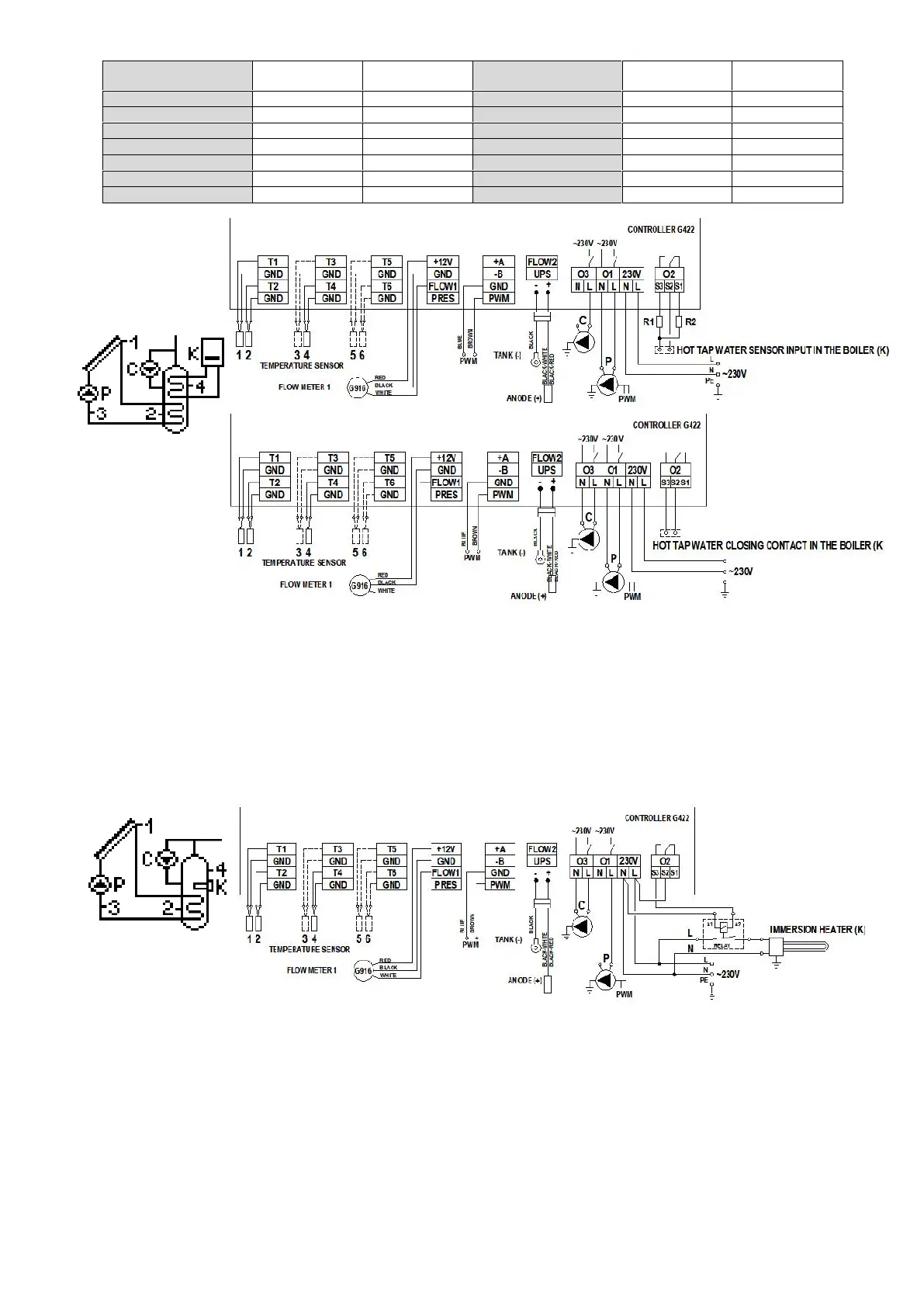
Fig. 5. Schematic and electrical diagram of installation no 3.
4.4 Tap water heating system - controlling solar collector pump, circulation pump and an electrical heater – scheme no 4
Controlling the P collector pump
Similarly as in scheme no 1 - description in point 4.1.
Controlling the C circulation pump
Similarly as in scheme no 2 - description in point 4.2.
Controlling electrical heater for tap water heating
Similarly as for the boiler in scheme no 3 - description in point 4.3.
The heater is switched on indirectly by passing voltage to transmitter coil which leads to a fault of appropriate connectors inside such a transmitter.
ATTENTION ! An additional relay adjusted to the power consumption of the electrical heater is needed to switch the heater on.
Fig. 6. Schematic and electrical diagram of installation no 4.
4.5. Tap water heating system - controlling solar collector pump, circulation pump and a heat pump – scheme no 5
Controlling the P collector pump
Similarly as in scheme no 1 - description in point 4.1.
Controlling the C circulation pump
Similarly as in scheme no 2 - description in point 4.2.
Controlling heat pump for tap water heating
Similarly as for the boiler in scheme no 3 - description in point 4.3.
The heat pump is switched on by a fault of appropriate connectors inside the heat pump.
 Loading...