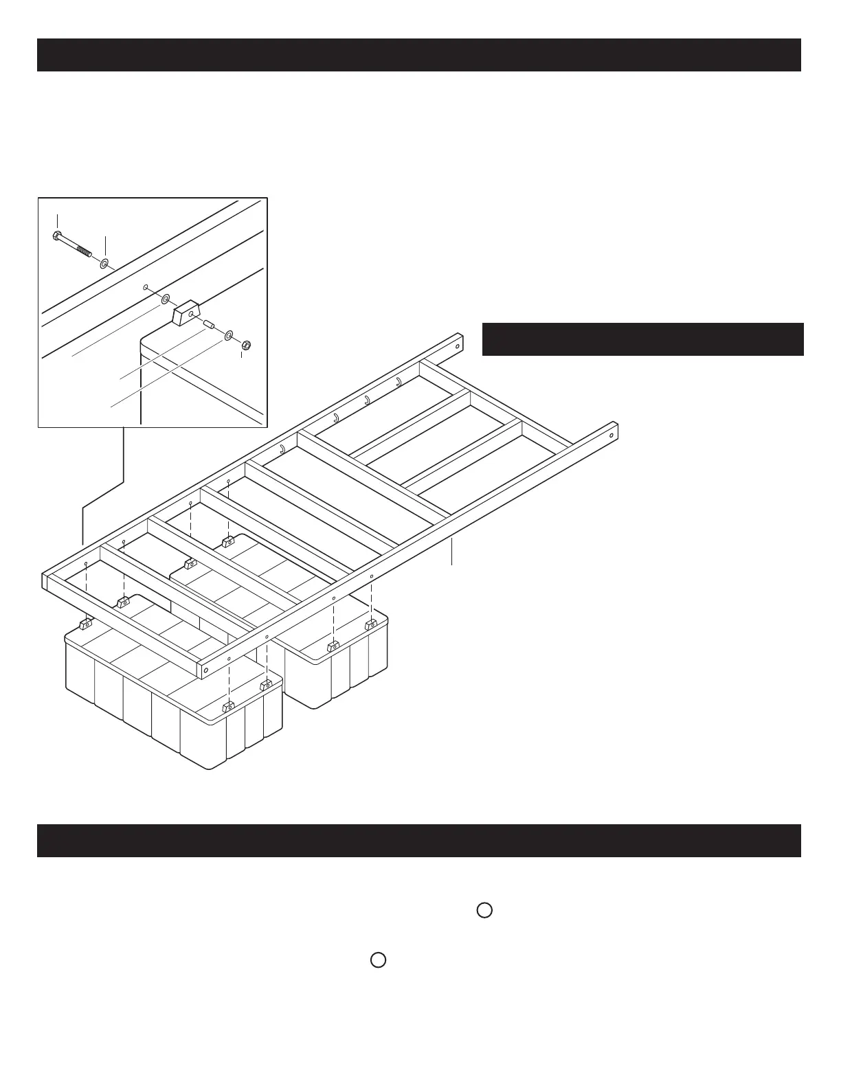
1/2” x 5-1/2” BOLT
1/2” WASHER
1/2” WASHER
1/2” x 2-1/4“ SPACER
1/2” WASHER
1/2”
NYLOCK NUT
LIFT FRAME
AIR TANK
AIR TANK (B)
WITH 90° HOSE
AIR TANK (A)
WITH STRAIGHT HOSE
CONNECTION
7‘ X 22’ LIFT FRAME
FRONT
PRE ASSEMBLY INSTRUCTIONS
TANK ASSEMBLY
Refer to enclosed parts list for description of parts and hardware. Note: The appearance of parts in
the assembly diagrams may vary somewhat for different size lifts.
Step 4: Before installation of the
tanks assure the interior
of the tank is free from
all visible defects and
tank is free from debris
(pieces of plastic) that
could prevent valves
from operating.
Step 1: These floating boat lifts are mainly designed for floating docks only,
and must have at least one finger walkway down one side of boat,
And require 5 1⁄2 feet of water depth at the back half of where
the boatlift will be installed.
Step 2: Separate all the bolts, nuts and other hardware from the
supplied crate.
Step 3: Assemble the lift on a flat surface. If a bolt is difficult to insert, use a
punch to line up the holes.
DRAWING 1
Position the tanks so the “A” tank
with the straight hose connection is
in the front and facing forward
and the “B” tank with the 90° hose
connection is in the back
facing forward.
Next attach the tanks to the frame using the
1⁄2” x 5-1/2” bolts. Insert one 1⁄2” washer at the
bolt head, one between the tank and the frame.
next insert the 1⁄2” x 2-1/4” spacer in the tank
mounting lug. Then secure with a 1⁄2” washer
and 1⁄2” nylock nut (see drawing 1). Repeat on
all other tank connections.
Step 5: Attach hose assembly “1A” to the straight hose connection B on the tank “A” and secure with a hose clamp
(see drawing 2 &6). Next attach the 192" hose to the “1A” hose assembly and secure with a hose clamp and
run the hose through the welded hose hangers on the frame (see drawing 3 & 6). Then attach the hose
assembly “1B” to the 90° hose connection C on tank “B” and secure with a hose clamp (see drawing 4 & 6).
Next attach the 56" hose to the valve on the “1B” hose assembly and secure with a hose clamp. Then attach
the other end to the 90° elbow on the “1A” hose assemblyand secure with a hose clamp (see drawing 5 & 6).
HOSE ASSEMBLY
(SEE NEXT PAGE FOR DRAWINGS 2-6)
Page 2 25 ft • 6000 LB • BoatPort
 Loading...