PAGE 7
© Copyright Hewland Engineering Limited
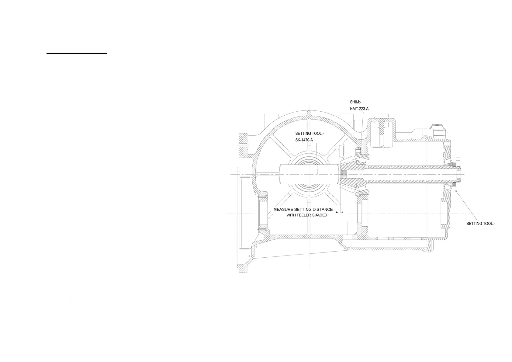
FIGURE 2
PINION SETTING
Requires special tool No.SK-1470-A & SK-1913
Press the pinion head bearing inner (37) onto the
pinion shaft (4). Fit the bearing housing (37) and
shims (40) into the maincase. Assemble the pinion
shaft into the maincase (1) and fit the bearing carrier
(2). Tighten the pinion shaft nut (111) onto the
pinion shaft until the pinion shaft requires 20-25
lbs.ins to turn it in it's bearings (equivalent to a
tangential force of 16-20 lbs at the outside diameter
of tool SK-1913)
Fit tool SK-1470-A into the maincase diff bearing
bore, and use feeler gauges to measure the gap
between the tool and the pinion front face. This
clearance should comply with the dimension
indicated on the pinion shaft label (also stamped on
the front face of the pinion shaft), and can be
adjusted by adding or removing shims (40) from
behind the pinion head bearing housing (37).
Alternatively, the pinion mounting distance can be
measured with a height gauge, and set to the
dimension on the pinion shaft label.
Note: It is not correct practice to replace a pinion
shaft without measuring the setting distance, even if
the old and new shafts have the same calibration.
SK-1913
 Loading...