Do you have a question about the Hi-Target Surveying Instrument ZTS-360R and is the answer not in the manual?
| Angle measurement method | Absolute Encoding |
|---|---|
| Accuracy | 2" |
| Measuring time (Fine) | 1.5 s |
| Measuring time (Tracking) | 0.8 s |
| Telescope magnification | 30x |
| Field of view | 1°30' |
| Minimum focusing distance | 1.5 m |
| Image | Erect |
| Data interface | RS-232C, USB |
| Compensator Range | ±3' |
| Compensator Accuracy | 1" |
| Operating Temperature Range | -20°C to +50°C |
| IP Rating | IP65 |
| Minimum reading | 1" / 5" |
| Distance measurement (Prism) | 5, 000m |
| Accuracy (Prism) | ±(2 mm + 2 ppm) |
| Accuracy (Reflectorless) | 3mm+2ppm |
| Operating time | 8 hours |
| Battery Type | Li-ion rechargeable battery |
Process for collecting user feedback on the instrument after purchase.
Instrument feature allowing measurement after power-on without azimuth loss.
System for easy file management, including data operations.
Enables measurement of various materials without a prism, even inaccessible targets.
Includes specialized programs for professional measuring tasks.
Allows for attaching a diagonal eyepiece for observing high-rise buildings.
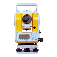
Identifies and labels the physical parts of the total station instrument.
Illustrates the display and keyboard layouts for the instrument's interfaces.
Details the functions and navigation for the angle measurement mode.
Explains the operation and soft keys for the distance measurement mode.
Describes the interface and soft keys for coordinate measurement operations.
Explains the process and options for saving measurement data and points.
Details the functionality and access to special settings via the star key.
Instructions for powering the instrument on and off.
Configuring the tilt sensor for accurate angle measurements.
Specifies the types of reflectors (prism, non-prism, board) that can be used.
Setting the constant value for the selected reflecting prism.
Explains the function of signal strength display for EDM.
Adjusting atmospheric parameters to improve distance measurement accuracy.
Automatic correction for atmospheric refraction and earth curvature.
Setting the minimum angular reading increment for measurements.
Configuring the automatic shutdown feature for power saving.
Enabling or disabling the rectangle beep sound.
Setting instrument constants like additive and multiplying factors.
Choosing or creating files for storing measurement and coordinate data.
Instructions for safely unpacking and storing the instrument.
Procedures for setting up and leveling the instrument on a tripod.
Procedures for handling the instrument's battery.
Information on selecting and using reflecting prisms.
Instructions for attaching and detaching the instrument's pedestal.
Steps for adjusting the eyepiece and aiming the telescope at the target.
Guide to inputting alphanumeric data and file names into the instrument.
Important precautions regarding the insertion and removal of USB drives.
Function to save measured angle data to a selected file.
Procedure for setting the horizontal angle to 0°00′00″.
Method for setting a desired horizontal angle manually.
Feature to hold the current horizontal angle reading.
Method for measuring angles repeatedly to improve accuracy.
Switching the display to show slope percentage (V%).
Enabling or disabling buzzer alerts for specific horizontal angle ranges.
Switching horizontal angle measurement between right (HR) and left (HL) modes.
Selecting display modes for vertical angles: Zenith (Vz) or Vertical (Vh).
Saving measured distance data to a selected file.
Initiating distance measurement and displaying results.
Selecting different EDM measurement modes (Single, Rept, Cont, Track).
Entering the offset measurement function for inaccessible points.
Initiating the distance stakeout function.
Performing angle offset measurements for difficult-to-reach targets.
Measuring coordinates using distance offset along observation direction.
Measuring points on a line using known distances between points.
Measuring points on a plane by defining three points.
Measuring points on a cylinder by determining tangency points.
Section for performing surveying operations.
Steps required before starting surveying, including file selection.
Setting the instrument station and backsight point for orientation.
Detailed steps for performing measurements within the surveying mode.
Procedure for finding earth points for designing points using stakeout.
Methods for selecting and inputting points for staking out.
Measuring new points using polar coordinates for staking out.
Calculating new point coordinates by measuring known points (ressection).
Interface for managing files, including dialogs, import, export, and formatting.
Importing external ASCII coordinate and code files into the instrument.
Importing files from a USB drive into the instrument.
Exporting measured data and files from the instrument.
Exporting files to a computer via a Mini USB port.
Re-creating the file system on the instrument's disk.
Displaying available disk space and data storage information.
Instructions for upgrading the instrument's software.
Accessing and overview of the instrument's various program functions.
Method for measuring distances and angles between multiple points (MLM).
Calculating and resetting the Z coordinate (elevation) of the station.
Calculating the area of a plane figure using measured or input coordinates.
Measuring deviation lengths and altitude differences relative to a baseline.
References chapter 10 for detailed roadway design and stakeout functions.
Accessing settings for unit, mode, and other instrument options.
Procedures for adjusting and calibrating instrument components.
Calibrating the instrument to correct index error (I.E).
Calibrating the instrument's tilt sensor along the X-axis.
Calibrating the instrument's tilt sensor along the Y-axis.
Configuring instrument settings, including additive and multiplication constants.
Selecting code files for use with the instrument.
Calculating and applying grid scale factors for distance measurements.
Configuring communication settings for RS232C or Bluetooth.
Inputting horizontal and vertical alignment data for roadway design.
Defining vertical alignment for roadway design using intersection points.
Procedure for staking out designed roadway points using input or imported files.
Checking and calibrating the instrument's tubular level.
Checking and calibrating the instrument's circular level.
Checking and calibrating the crosshair reticle within the telescope.
Checking and calibrating the perpendicularity between collimation and cross axes.
Automatic compensation for the vertical plate index zero error.
Checking and setting the vertical index error and zero point.
Checking and calibrating the instrument's centering device.
Checking and calibrating the instrument's additive constant (K).
Checking the parallelism between collimation and photoelectric axes.
Procedures and precautions for non-prism ranging measurements.
