VertX EVO V1000 User Guide, 71000-901, Rev. A.4
Page 10 of 25 July 2016
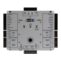
4. Output Connections (VertX EVO V1000): All Output connections are used for
general purpose controls. The following table shows where the various outputs are
located. Pin numbers shown use the convention “NO/C/NC”.
For example, Output 1, V1000: P14 Pin 3 is NO (Normally Open)
Pin 4 is C (Common) and Pin 5 is NC (Normally Closed).
Note: Relays are dry contact rated for 2Amps @ 30VDC.
1 P14 Pins 3/4/5
CAUTION: Some magnetic locks exhibit both high in-rush current when activated
and a high instantaneous break voltage when de-energized due to magnetic field
collapse. Use a snubber circuit across the controlling relay terminals to protect the
controlling relay contacts. Go to support.hidglobal.com, see Solution 891 - How do
I wire a High In-Rush Current locking device to VertX/Edge/Edge Solo?
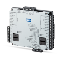
5. Input Connections: Input connections are analog inputs used for a combination of
specific functions such as Request-to-Exit (REX), Door monitor, etc. They can also be
used as general purpose monitoring. Connect one side of the switch or contact to the
+ (plus) lead and the other to the – (minus) lead. The following table shows where the
inputs are located. Pin numbers shown on the cover use the convention +/–.
The default REX input configuration is normally open (NO) unsupervised (no EOL
resistors).
However, the default Door Switch (DS) configuration is Normally Closed (NC),
unsupervised (no EOL resistors).
All other input points are defaulted for NO switches and are unsupervised (no EOL
resistors).
Any input can be configured as NO or NC, as well as unsupervised or supervised.

 Loading...