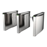
Figure 4-2 Components 2
Note
• For details about wiring arrangement, refers to the actual device.
• If the
turnsle contains two lanes, standing at the entrance posion, the IR modules on the le
pedestal are the IR sending modules. The IR modules on the right pedestal are the IR receiving
modules. The IR modules on the le side of the middle pedestal are the IR receiving modules,
while the IR modules on the right side of the middle pedestal are the IR sending modules.
• Warning tags can be viewed on the side panel of each pedestal.
• Safety
Instrucons can be viewed on the middle panel inside the pedestal.
4.2 Wiring Electric Supply
Wire electric supply with the switch in the pedestal. Terminal L and terminal N are on the switch,
while terminal PE should connect to a ground wire (yellow and green wire).
DS-K3Y501SX Series Flap Barrier Quick Start Guide
10
 Loading...