Barrier Gate User Manual
61
assembling bolts. Save the components and parts for the following installations.
2. Disassemble the boom pole and chuck.
Figure 4-3 Disassemble Boom Pole and Chuck
3. Unscrew the M12 fixing bolt of the spindle rod anticlockwise with a 10 mm hex wrench, and
disassemble the bolt.
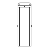
Figure 4-4 Disassemble Bolt
4. Loosen the barrier gate control box captive screw with the screwdriver, and then rotate the
control box (more than 160°).
5. Loosen the M8 × 20 hex socket head cap screw and M8 nut on the side of the spindle rod with
a No. 6 hex wrench and an adjustable wrench.
 Loading...