EasyManua.ls Logo

HIKVISION DS-TMG520-M/A/B - Page 40

HIKVISION DS-TMG520-M/A/B
81 pages
To Next Page IconTo Next Page
To Previous Page IconTo Previous Page
Loading...
Barrier Gate User Manual
34
Radar Brown Line
Radar Yellow Line
Anti-fall
Radar
AC34V
Nixie
Tube
Motor
Connection
Resistance
Connection
Encoder
Network
Interface
Green Light
Red Light
COM
Barrier Gate
Control Box
Rise Stop
Fall Learn
Rising Control
+
Rising Control
-
Falling Control
+
Falling Control
-
Stopping Control
+
Stopping Control
-
+5V/GND
Rise via Hand Shank
Fall via Hand Shank
Stop via Hand Shank
GND
RS-485-B2
RS-485-A2
5V
GND
RS-485-B
RS-485-A
Induction Input
+
Induction Input
-
Protection Input
+
Protection Input
-
GND
+12V
Bollard Control
2+
Bollard Control
2 -
Bollard Control
1 -
Falling Limit Output
1+
Falling Limit Output
1 -
Rising Limit Output
1+
Rising Limit Output
1 -
Alarm Input
1 +
Alarm Input
1 -
Alarm Input
2 +
Alarm Input
2 -
12V_IN
LED_ARR1
LED_ARR2
GND
12V_OUT
Bollard Control
1 +
Figure 2-42 Connect to Anti-fall Radar
Note
Radar 12 V power supply output: 0.5 AAV, max. 1 A.
Induction/protection input withstanding voltage: max. 12 VDC.
12 V refers to internal power supply of the device. External power supply is not supported.
Radar Installation Instructions
The anti-fall radar should be installed beside the barrier gate. In different scenarios, follow the
instructions below to get the best effect.
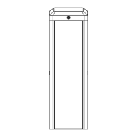
Scenario 1: Small-Sized Vehicles
For small-sized vehicles, such as the cars and SUVs, install the radar according to the figure shown
below.

Related product manuals