DEMOLITION HAMMER
SAFETY SHEET
(Hilti TE1000-AVR)
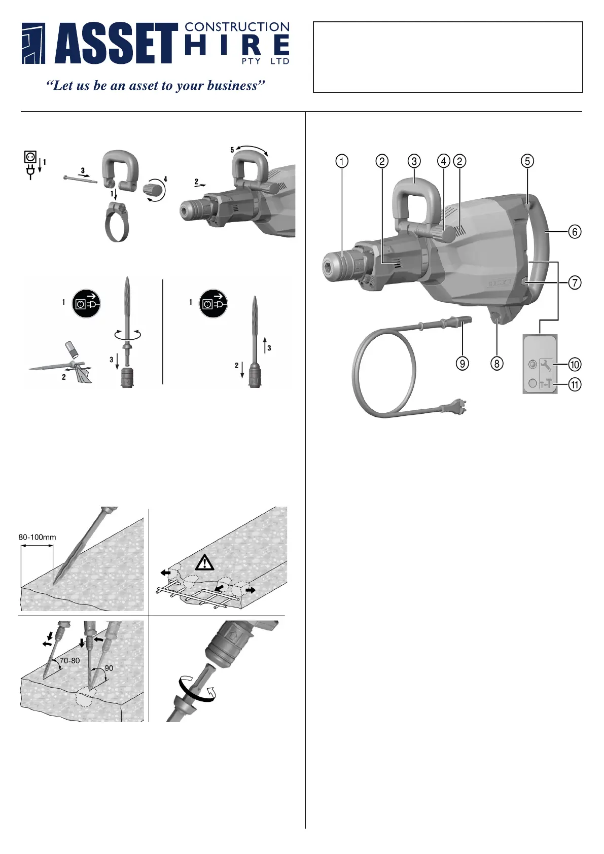
MAIN COMPONENTS
English 5
3 Description
3.1 Product overview
Printed: 24.01.2017 | Doc-Nr: PUB / 5165549 / 000 / 05
@
Chuck
;
Air vents
=
Side handle
%
Knob
&
On/off switch
(
Grip
)
Power level selector switch
+
Connector on electric tool
§
Supply cord with keyed, releasable plug
connector
/
Service indicator
:
Power level indicator
3.2 Intended use
The product described is an electrically powered breaker for heavy chiseling work.
It is designed for breaking or demolishing concrete, masonry, stone and asphalt.
▶ Operation is permissible only when connected to a power source providing a voltage and frequency in
compliance with the information given on the type identification plate.
3.3 Possible misuse
This product is not suitable for working on hazardous materials.
This product is not suitable for working in a damp environment.
3.4 Active Vibration Reduction (AVR)
The breaker is equipped with an Active Vibration Reduction (AVR) system, which reduces vibration
significantly.
3.5 Power level indicator
The breaker is equipped with a power level indicator LED.
Chiseling power can be reduced to approx. 70% by pressing the power level selector switch. The power
level LED then lights up, indicating reduced power.
3.6 Service indicator information
The breaker is equipped with a service indicator LED.
Status Meaning
The service indicator lights red. • End of service interval – servicing is due.
• A fault has occurred in the tool.
The service indicator blinks red. • The overheating prevention cut-out has been
activated.
• The voltage provided by the electric supply is
too high.
Note
Bring the product to Hilti Service in good time. This will help to ensure that it’s always ready for use.
3.7 Items supplied
Breaker, side handle, operating instructions.
You can find other system products approved for your product at your local Hilti Center or online at:
www.hilti.com.
4 Technical data
4.1 Breaker
Note
For details of the rated voltage, current, frequency and/or input power, please refer to the power tool’s
country-specific type identification plate.
When powered by a generator or transformer, the generator or transformer’s power output must be at least
twice the rated input power shown on the rating plate of the power tool. The operating voltage of the
transformer or generator must always be within +5% and -15% of the rated voltage of the power tool.
Printed: 24.01.2017 | Doc-Nr: PUB / 5165549 / 000 / 05
6 English
@
Chuck
;
Air vents
=
Side handle
%
Knob
&
On/off switch
(
Grip
)
Power level selector switch
+
Connector on electric tool
§
Supply cord with keyed, releasable plug
connector
/
Service indicator
:
Power level indicator
3.2 Intended use
The product described is an electrically powered breaker for heavy chiseling work.
It is designed for breaking or demolishing concrete, masonry, stone and asphalt.
▶ Operation is permissible only when connected to a power source providing a voltage and frequency in
compliance with the information given on the type identification plate.
3.3 Possible misuse
This product is not suitable for working on hazardous materials.
This product is not suitable for working in a damp environment.
3.4 Active Vibration Reduction (AVR)
The breaker is equipped with an Active Vibration Reduction (AVR) system, which reduces vibration
significantly.
3.5 Power level indicator
The breaker is equipped with a power level indicator LED.
Chiseling power can be reduced to approx. 70% by pressing the power level selector switch. The power
level LED then lights up, indicating reduced power.
3.6 Service indicator information
The breaker is equipped with a service indicator LED.
Status Meaning
The service indicator lights red. • End of service interval – servicing is due.
• A fault has occurred in the tool.
The service indicator blinks red. • The overheating prevention cut-out has been
activated.
• The voltage provided by the electric supply is
too high.
Note
Bring the product to Hilti Service in good time. This will help to ensure that it’s always ready for use.
3.7 Items supplied
Breaker, side handle, operating instructions.
You can find other system products approved for your product at your local Hilti Center or online at:
www.hilti.com.
4 Technical data
4.1 Breaker
Note
For details of the rated voltage, current, frequency and/or input power, please refer to the power tool’s
country-specific type identification plate.
When powered by a generator or transformer, the generator or transformer’s power output must be at least
twice the rated input power shown on the rating plate of the power tool. The operating voltage of the
transformer or generator must always be within +5% and -15% of the rated voltage of the power tool.
Printed: 24.01.2017 | Doc-Nr: PUB / 5165549 / 000 / 05
FITTING AND ADJUSTING SIDE HANDLE
8 English
▶ Fit or adjust the side handle.
Note
The instructions provided with the side handle must also be observed.
5.1.2 Detachable supply cord
CAUTION
Risk of injury! Due to leakage current as a result of dirty contacts.
▶ Connect the detachable electric connector to the electric tool only when it is clean and dry and
when the supply cord is unplugged from the power outlet.
▶ Connect / disconnect the detachable supply cord.
5.1.2.1 Connecting the detachable supply cord
CAUTION
Risk of injury! Due to leakage current as a result of dirty contacts.
▶ Connect the detachable electric connector to the electric tool only when it is clean and dry and
when the supply cord is unplugged from the power outlet.
1. Push the keyed, detachable electric plug connector into the socket as far as it will go, until it is heard to
engage.
2. Plug the supply cord into the power outlet.
5.1.2.2 Disconnecting the detachable supply cord
1. Unplug the supply cord from the power outlet.
2. Press the release button and pull the keyed, detachable electric plug connector out of the socket.
3. Pull the supply cord connector out of the power tool.
Printed: 24.01.2017 | Doc-Nr: PUB / 5165549 / 000 / 05
FITTING AND REMOVING ACCESSORY TOOL
English 9
5.1.3 Fitting the accessory tool
1. Apply a little grease to the connection end of the accessory tool.
2. Push the accessory tool into the chuck as far as it will go, turning it and applying light pressure until it
engages with an audible click.
◁ The product is ready for use.
Note
Use only the recommended grease supplied by Hilti. Use of unsuitable grease may cause damage
to the product.
5.1.4 Removing the accessory tool
WARNING
Risk of injury! The accessory tool gets hot during use and may also have sharp edges.
▶ Wear protective gloves when changing the tool.
DANGER
Risk of fire! Risk of contact between the hot accessory tool and highly inflammable materials.
▶ Do not lay the hot accessory tool down on highly inflammable materials.
1. Pull the chuck back.
2. Remove the accessory tool.
Printed: 24.01.2017 | Doc-Nr: PUB / 5165549 / 000 / 05
FITTING:
1. Apply a little grease to the connection end of the accessory tool.
2. Push the accessory tool into the chuck as far as it will go, turning it
and applying light pressure until it engages with an audible click.
REMOVAL
1. Pull the chuck back.
2. Remove the accessory tool.
CHISELING
10 English
5.2 Types of work
Warning! Risk of damage!
▶ Operation of the direction of rotation and/or function selector switch while the tool is running may
result in damage to the tool.
▶ Do not operate this switch while the tool is running.
Observe the safety instructions and warnings in this documentation and on the product.
5.2.1 Chiseling
Note
The chisel can be adjusted to 6 different positions (in 60° increments). This ensures that flat chisels
and shaped chisels can always be set to the optimum working position.
If inadequate pressure is applied, the chisel will jump around uncontrollably. Application of excessive
pressure will result in a loss of chiseling performance.
1. Plug the supply cord into the power outlet.
2. Bring the chisel into contact with the workpiece about 80 -100 mm (3¹⁄₈" - 4") from its edge.
3. Begin with the chisel positioned at an angle of 70° to 80° to the concrete surface, with the tip of the chisel
pointing toward the edge of the workpiece. Break material away by subsequently increasing the angle to
approx. 90° as the chisel penetrates.
◁ When working close to reinforcing bars, always guide the tip of the chisel toward the edge of the
workpiece, not toward a reinforcing bar.
4. Rotate the chisel regularly to help ensure even wear and to promote the self-sharpening process.
Printed: 24.01.2017 | Doc-Nr: PUB / 5165549 / 000 / 05
1. Plug the supply cord into the power outlet.
2. Bring the chisel into contact with the workpiece about 80 -100 mm
from its edge.
3. Begin with the chisel positioned at an angle of 70° to 80° to the
concrete surface, with the tip of the chisel pointing toward the edge of
the workpiece. Break material away by subsequently increasing the
angle to approx. 90° as the chisel penetrates. When working close to
reinforcing bars, always guide the tip of the chisel toward the edge of
the workpiece, not toward a reinforcing bar.
4. Rotate the chisel regularly to help ensure even wear and to promote
the self-sharpening process.

 Loading...