DEMOLITION HAMMER
SAFETY SHEET
(Hilti TE3000-AVR)
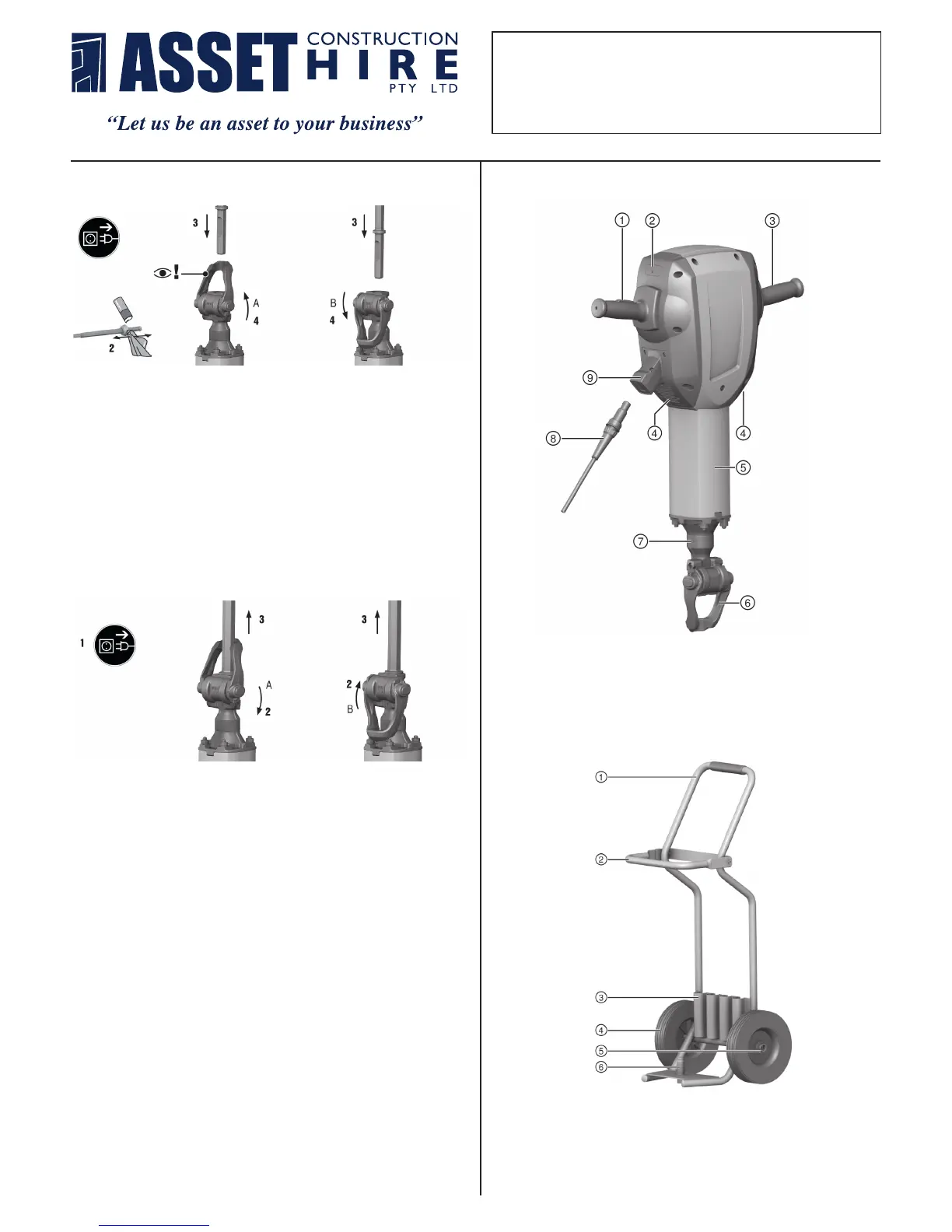
MAIN COMPONENTS
English 7
3 Description
3.1 Overview of the product
Printed: 31.05.2017 | Doc-Nr: PUB / 5070852 / 000 / 06
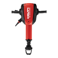
FITTING THE ACCESSORY TOOL
1. Apply a little grease to the connection end of the accessory tool.
2. Open the locking bar.
3. Push the accessory tool into the chuck as far as it will go.
4. For accessory tools with a collar, bring the retaining bar into locking
position A.
5. For accessory tools with a locking groove, bring the retaining bar into
locking position B. Position the chisel so that the groove is facing
locking position B.
6. Check that the chisel has engaged correctly by gripping and pulling it.
Insert tools with a combined connection end (with collar and groove)
can be locked in position A or B, as desired.
@
On/off switch
;
Service indicator
=
Grip
%
Air vents
&
Guide tube
(
Accessory tool retainer / locking bar
)
Chuck
+
Supply cord with keyed, releasable plug
connector
§
Connector on electric tool
Printed: 31.05.2017 | Doc-Nr: PUB / 5070852 / 000 / 06
8 English
@
On/off switch
;
Service indicator
=
Grip
%
Air vents
&
Guide tube
(
Accessory tool retainer / locking bar
)
Chuck
+
Supply cord with keyed, releasable plug
connector
§
Connector on electric tool
Printed: 31.05.2017 | Doc-Nr: PUB / 5070852 / 000 / 06
English 11
3.2 Transport trolley components
Printed: 31.05.2017 | Doc-Nr: PUB / 5070852 / 000 / 06
Holder for accessory tools (chisels)
%
Wheels
&
Wheel securing parts (washer, retaining pin)
(
Power tool locating pin
3.3 Intended use
The product described is a hand-held electric breaker with 28 mm hex chuck. It is designed for chiseling
work on concrete, masonry and asphalt. Excavation and compacting are further possible applications.
▶ Operation is permissible only when connected to a power source providing a voltage and frequency in
compliance with the information given on the type identification plate.
3.4 Possible misuse
This product is not suitable for working on hazardous materials.
This product is not suitable for working in a damp environment.
3.5 Service indicator
The breaker is equipped with a service indicator LED.
Status Meaning
The service indicator lights red. • End of service interval – servicing is due.
• A fault has occurred in the tool.
The service indicator blinks red. • Protection against overheating
• The voltage provided by the electric supply is
too high.
Note
Bring the product to Hilti Service in good time. This will help to ensure that it’s always ready for use.
3.6 Active Vibration Reduction (AVR)
The breaker is equipped with an Active Vibration Reduction (AVR) system, which reduces vibration
significantly.
3.7 Items supplied
Breaker, operating instructions with bag to attach to the transport trolley, grease.
The transport trolley is available as an accessory.
Note
You can find other system products approved for your product at your local Hilti Center or online at:
www.hilti.comgroup
4 Technical data
Note
For details of the rated voltage, frequency, current and input power, please refer to the power tool’s
country-specific type identification plate.
When powered by a generator or transformer, the generator or transformer’s power output must be at least
twice the rated input power shown on the rating plate of the power tool. The operating voltage of the
transformer or generator must always be within +5% and -15% of the rated voltage of the power tool.
TE 3000AVR
Weight in accordance with EPTA proce-
dure 01
29.9 kg
Single impact energy in accordance with
the EPTA procedure
68 J
Printed: 31.05.2017 | Doc-Nr: PUB / 5070852 / 000 / 06
12 English
@
Grip
;
Locking bar
=
Holder for accessory tools (chisels)
&
Wheel securing parts (washer, retaining pin)
(
Power tool locating pin
3.3 Intended use
The product described is a hand-held electric breaker with 28 mm hex chuck. It is designed for chiseling
work on concrete, masonry and asphalt. Excavation and compacting are further possible applications.
▶ Operation is permissible only when connected to a power source providing a voltage and frequency in
compliance with the information given on the type identification plate.
3.4 Possible misuse
This product is not suitable for working on hazardous materials.
This product is not suitable for working in a damp environment.
3.5 Service indicator
The breaker is equipped with a service indicator LED.
Status Meaning
The service indicator lights red. • End of service interval – servicing is due.
• A fault has occurred in the tool.
The service indicator blinks red. • Protection against overheating
• The voltage provided by the electric supply is
too high.
Note
Bring the product to Hilti Service in good time. This will help to ensure that it’s always ready for use.
3.6 Active Vibration Reduction (AVR)
The breaker is equipped with an Active Vibration Reduction (AVR) system, which reduces vibration
significantly.
3.7 Items supplied
Breaker, operating instructions with bag to attach to the transport trolley, grease.
The transport trolley is available as an accessory.
Note
You can find other system products approved for your product at your local Hilti Center or online at:
www.hilti.comgroup
4 Technical data
Note
For details of the rated voltage, frequency, current and input power, please refer to the power tool’s
country-specific type identification plate.
When powered by a generator or transformer, the generator or transformer’s power output must be at least
twice the rated input power shown on the rating plate of the power tool. The operating voltage of the
transformer or generator must always be within +5% and -15% of the rated voltage of the power tool.
TE 3000AVR
Weight in accordance with EPTA proce-
dure 01
29.9 kg
Single impact energy in accordance with
the EPTA procedure
68 J
Printed: 31.05.2017 | Doc-Nr: PUB / 5070852 / 000 / 06
14 English
Observe the safety instructions and warnings in this documentation and on the product.
5.1.1 Fitting the accessory tool
Note
Check the accessory tool for damage or uneven wear each time before use and replace it if necessary.
Check that the locking bar is clean and undamaged.
1. Apply a little grease to the connection end of the accessory tool.
2. Open the locking bar.
3. Push the accessory tool into the chuck as far as it will go.
4. For accessory tools with a collar, bring the retaining bar into locking position A.
5. For accessory tools with a locking groove, bring the retaining bar into locking position B.
◁ Position the chisel so that the groove is facing locking position B.
6. Check that the chisel has engaged correctly by gripping and pulling it.
◁ Insert tools with a combined connection end (with collar and groove) can be locked in position A or
B, as desired.
Note
Use only the recommended grease supplied by Hilti. Use of unsuitable grease may cause damage
to the product.
5.1.2 Removing the accessory tool
WARNING
Risk of injury! The accessory tool gets hot during use and may also have sharp edges.
▶ Wear protective gloves when changing the tool.
DANGER
Risk of fire! Risk of contact between the hot accessory tool and highly inflammable materials.
▶ Do not lay the hot accessory tool down on highly inflammable materials.
WARNING
Risk of injury! Risk of burning injuries caused by hot surfaces.
▶ Avoid touching the guide tube as this part gets hot through use of the power tool.
Printed: 31.05.2017 | Doc-Nr: PUB / 5070852 / 000 / 06
REMOVING THE ACCESSORY TOOL
1. Open the locking bar.
2. Pull the accessory tool out of the chuck.
English 15
1. Open the locking bar.
2. Pull the accessory tool out of the chuck.
5.2 Detachable supply cord
CAUTION
Risk of injury! Due to leakage current as a result of dirty contacts.
▶ Connect the detachable electric connector to the electric tool only when it is clean and dry and
when the supply cord is unplugged from the power outlet.
▶ Connect / disconnect the detachable supply cord.
5.2.1 Connecting the detachable supply cord
1. Push the keyed releasable electric connector into the socket on the power tool as far as it will go.
2. Turn the plug connector clockwise until it is heard to engage.
3. Plug the supply cord into the power outlet.
5.2.2 Disconnecting the detachable supply cord
1. Unplug the supply cord from the power outlet.
2. Turn the keyed releasable electric connector counterclockwise as far as it will go.
3. Pull the supply cord connector out of the power tool.
6 Care and maintenance
WARNING
Danger of electric shock! Carrying out care and maintenance while the supply cord is connected to
the power outlet presents a risk of serious injuries including burns.
▶ Always unplug the supply cord before carrying out all care and maintenance tasks.
Care
• Carefully remove stubborn dirt from the tool.
• Clean the air vents carefully with a dry brush.
• Use only a slightly damp cloth to clean the casing. Do not use cleaning agents containing silicone as
they can attack the plastic parts.
Maintenance
WARNING
Danger of electric shock! Improper repairs to electrical components may lead to serious injuries
including burns.
▶ Repairs to the electrical section of the tool or appliance may be carried out only by trained electrical
specialists.
Printed: 31.05.2017 | Doc-Nr: PUB / 5070852 / 000 / 06
 Loading...