29
Operating
4.2 System enabling
4.2.1 Enabling by the front panel key switch
! Verify that the zone status LEDs and are turned off.
If they’re switched on it’s necessary to close the doors and windows relative to the zone
signalled opened. It’s also possible that the zone signalled opened could be the one
relative to the volumetric detectors; in this case the exiting time will allow to exit the
protected area without activating the alarm.
! Turn the key switch in the “ON” position.
! The green LED “EXIT” starts blinking indicating the exiting time, in which to leave the
protected areas.
! When the exiting time is finished, the green LED "EXIT" turns off indicating that the
system is enabled.
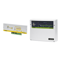
4.2.2 Enabling by other command system
If an electronic key system, a proximity key system, or an electronic keypad system is
installed outside of the protected areas, it's necessary to leave the key switch ALWAYS in the
“ON” position.
All the SKI connector for the electronic
key, the PXR reader for the proximity key
and the KBC, KBM and KBT keypads have
two LEDs, one green and one red,
indicating the central unit status (see table
beside).
To enable the system:
! Verify that the red LED is turned off.
If it's turned on, it's necessary to close
the opened doors or windows relative
to the zone that is signalled opened in
the central unit.
! Insert the electronic key, or approach
the proximity key to the reader, or digit
the code on the keypad.
! The green LED turns off indicating that
the system is enabled.
3 4
1
8
8
1
GREEN
LED
RED
LED
BOTH
ON
System
disabled
Opened
zone/s
Alarm
memory
OFF
System
enabled
Closed
zones
FLASH
System
disabled
Exiting
time
GREEN
LED
RED
LED
security
28
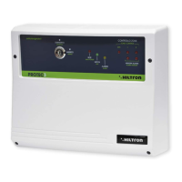
4 Operating
4.1 Front panel description
Key switch
Allows to enable / disable the system. If there's
an electronic key or another command system ,
this switch has always to be turned on the “ON”
position.
Zone 24h status control LED
on opened zone
off closed zone
Zone 1 status control LED
on opened zone
off closed zone
Zone 2 status control LED
on opened zone
off closed zone
Fuse service output F2 (1A)
Fuse sirens output F1 (3A)
"ALARM MEMORY" LEDs
On system disabled, if the LED “ALLARME”
flashes, these LEDs indicate which zone
caused the alarm.
Yellow LED “ALARM”
on during the entering time
or in alarm condition
blinking ALARM MEMORY
(see 7 e 8 to identify the
zone that caused the
alarm)
Green LED “EXIT”
on system disabled
blinking during the exiting time
off system enabled
Red LED “POWER”
on presence of main supply
off absence of main supply
7
3
4
PROTEC3 - User’s manual
1
2
7
8
9
security
43
1
8 7
2
11
10
9
6
5
5
6
10
11