4 Operating
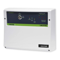
4.1 Front panel description
Key switch Allows to enable / disable the system
LED “ALARM”
On During entering time
Blinking Alarm memory
LED “EXIT”
On System disable
Blinking During exiting time
Off System enable
LED “POWER”
On Presence of main supply
Off Absence of main supply
Zone 24h status control LED
On Opened zone
Off Closed zone
Blinking Auto-excluded
Push-button “ALARM MEMORY”
Pressed Memory alarm visualization (LEDs )
Release (except TM400P and PROTEC4) Zone status check
Zone status control LED
On Opened zone
Off Closed zone
Flash (except TM400P and PROTEC4) Excluded zone
Blinking (except TM400P and PROTEC4) Alarm memory (pressing the push-button )
Excluded/inclused zone push-button
28 29
4
4.2 Enabling / disabling by the front panel key switch
4.2.1 Enabling
! Verify that the zone status LEDs are turned off.
If they’re switched on it’s necessary to close the doors and windows relative to the zone
signalled opened. It’s also possible that the zone signalled opened could be the one
relative to the volumetric detectors; in this case the exiting time will allow to exit the
protected area without activating the alarm.
! Turn the key switch in the “ON” position.
! The green LED “EXIT” starts blinking indicating the exiting time, in which to leave the
protected areas.
! When the exiting time is finished, the green LED "EXIT" turns off indicating that the
system is enabled.
4.2.2 Disabling
! Open the entering door.
! The yellow LED “ALARM” is lit. The alarm will not activates immediately becouse the
entering door is usually protected by the delayed zone 1: the entering time will allows to
reach the central unit to disable the system.
! Turn the key switch in the “ST/BY” position
! The green LED “ALARM” turns off indicating that the system is disabled, while the
yellow LED "ALARM" bilnking if the memory alarm is on.
Serie TM / Serie PROTEC burglary central unit - User’s manual Operating
RETE
ALLARME
USCITA
24H
ZONA
1
ZONA
2
ZONA
3
ZONA
4
ZONA
5
ZONA
6
ZONA
7
ZONA
8
ESCLUSIONE
CONTROLLO
INSERITO
DISINSERITO
only TM400P e PROTEC4 (points 6/7)
(DISARM)
(ARM)
(ALARM)
(EXIT)
(POWER)
(EXCLUSION)
(CONTROL)
(ZONES)
5
7
1
3
3
2
1
2
3
ALARM
LED
EXIT
LED
Exiting
time
ON OFFBLINKING ON OFFBLINKING
System DISABLE
System ENABLE
System
disable
System
enable
Allarme
Mem. allarme
Entering
time
Alarm
memory:
see and
5
6
security security