F 6221 (0625)
318
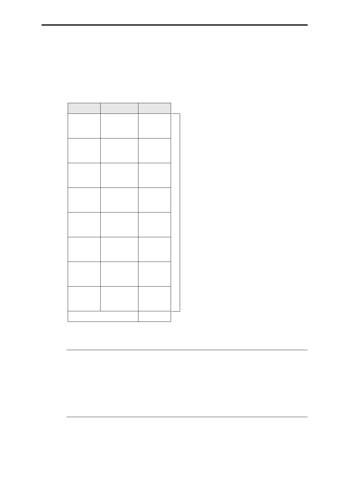
3 Pin allocation (in the field)
Channel 7 and 8 have no supply
• Cable type: Z 7063/6221/ExCn/ITI +
Z 7025/3325/ExCx
part no. 93 6221 101
Z 7063/6221/ExCn/ITI/R2 part no. 93 6221 103
Note The grounds (I1- to I8-) on the module are taken together to one
ground (I-). The signals (I1- to I8-) may only be interconnected on the
module.
No external joints are allowed.
In Ex applications, the cable shield has to be connected to the equipo-
tential bonding. In non Ex applications, the cable shield is connected
to the PE terminal / bus bar on the subrack.
Channel Connection Color
I1+
TC1+
z2
z18
WH
BN
I2+
TC2+
z4
z20
GN
YE
I3+
TC3+
z6
z22
GY
PK
I4+
TC4+
z8
z24
BU
RD
I5+
TC5+
z10
z26
BK
VT
I6+
TC6+
z12
z28
GY-PK
RD-BU
I7+
I7-
z14
d14
WH-GN
BN-GN
I8+
I8-
z16
d16
WH-YE
YE-BN
Cable screen YEGN
Cable
LiYCY
8x2 x 0.2 mm
2
screened
 Loading...