Operating Keys and LED
START
Starts measurement. The LED at the right lights green while measuring.
STOP
Stops measurement.
SAVE
Press to save data manually.
SCROLL/CURSOR
Use the left and right keys to scroll through the waveform in either direction or
move the A/B cursors accordingly.
MONITOR
Displays the current input state as a waveform or numerical values. (The data
is not recorded in internal buffer memory.)
WAVE
Switches to the waveform screen display.
SET
Displays the Settings screens, and toggles among the screen tabs with each
press.
FILE
Displays file information.
POWER LED
Lights when the power is turned on.
CHARGE LED
Lights when the Z1000 Battery Pack is charging.
PRESETS
Allows you to set measurement conditions by follow-
ing the instructions on the screen.
Cursor Keys
Moves the position of the cursor (blinking selection)
on the screen.
ENTER
Accepts displayed settings.
KEY LOCK
To lock the keys, press and hold the left
and right cursor keys for three seconds.
Repeat to unlock.
ESC
Cancels changes to settings.
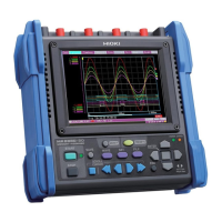
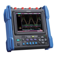
MR8880-20
MEMORY HiCORDER
Measurement Guide
June 2011 Edition 1 Printed in Japan
MR8880B981-00 11-06H
This measurement guide provides several measurement examples
available with Model MR8880-20 using the instrument’s “PRE-
SETS” feature. Because only the minimum instructions are avail-
able here, please study the detailed instruction manual carefully
before actually using the instrument.
1. Display the measurement guide screen.
(See page 1.)
2. Select “Measure Power Supply on INSTNT”.
3. Configure the settings as shown below.
4. Select “Start measurement”.
The start confirmation dialog will be displayed.
5. Press the START key to begin measuring.
The MR8880-20 will measure ONCE, and display a
waveform like that shown below.
Measuring a 100 V AC Waveform
How to measure 5 cycles of the waveform level (instanta-
neous value) of a 100 V AC/60 Hz voltage waveform once
Select
Apply
4
Select
Apply
2
• When measuring quick-changing signals such as power wave-
forms or sudden transients, use the "Highspeed" function.
T
0.00 V
Trigger point
• For this example, a trigger has
been set to start measurement
when the signal reaches 0V. The
trigger point (measurement start
point) is shown on the right.
1. Display the measurement guide screen.
(See page 1.)
2. Select “Measure Power Supply on RMS”.
3. Configure the settings as shown below.
4. Select “Start measurement”.
The start confirmation dialog will be displayed.
5. Press the START key to begin measuring.
The MR8880-20 will measure for 1 minute, and then
display a waveform like that shown below.
Measuring 100 V AC RMS
How to measure the RMS level of the voltage fluctuation
of a 100 V AC/60 Hz commercial power supply for 1 min-
ute
Select
Apply
4
Select
Apply
2
• When measuring the RMS fluctuation of a power supply or cap-
turing the long-term changes of slow-moving phenomena, use the
"Realtime" function.
• To measure and save data to external media at the same time,
insert a CF Card or USB flash drive into the MR8880-20, and con-
figure the device according to Step 3 in "Save Measurement
Data". Please refer to the detailed instruction manual for further
information.