30
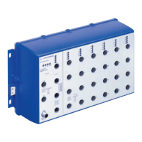
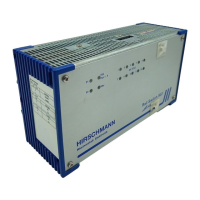
Installation GRS1020/1120/1030/1130
Release
03
01/2017
The USB interface has the following properties:
Supplies current of max. 500 mA
Voltage not potential-separated
Connectors: type A
Supports the USB master mode
Supports USB 2.0
1.9 Signal contact
Figure 1: Signal contact: 2-pin terminal block with screw locking
The signal contact is a potential-free relay contact.
The device allows you to perform remote diagnosis via the signal contact. In
the process, the device signals events such as a line interruption. When an
event occurs, the device opens the relay contact and interrupts the closed
circuit. The management setting specifies which events switch a contact.
You can also use the management to switch the signal contact manually and
thus control external devices.
Figure Pin Operation
1VCC (VBus)
2 − Data
3 + Data
4 Ground (GND)
Table 12: Pin assignment of the USB interface
 Loading...