Do you have a question about the Hisense HK570 and is the answer not in the manual?
Provides critical safety instructions and warnings for operating the POS terminal.
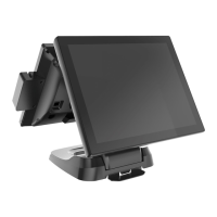
Introduces the product and mentions potential design changes for quality improvement.
Details the technical specifications of the HK570 Touch Terminal, including CPU, memory, storage, and ports.
Illustrates and labels the components visible from the front of the terminal.
Illustrates and labels the components visible from the back of the terminal.
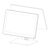
Provides the physical dimensions of the HK570 Touch Terminal in diagrams.
Details the input/output ports available on the terminal with a diagram.
Guides on selecting a suitable and safe location for installing the terminal.
Explains how to remove covers to access ports before connecting external devices.
Provides instructions and cautions for connecting the DC power supply cable.
Details the procedure for tightening the tool-less screw on the base for stability.
Introduces the location of POS drivers and utilities, typically found on a CD.
Explains how to set up and use a dual monitor configuration with the system.
Shows a detailed diagram of the motherboard with numbered components.
Lists all connectors on the motherboard and their respective functions.
Describes the function and settings for various jumpers on the motherboard.
Details the display interface types and connection pin definitions for LVDS.
Provides details on the audio codec and onboard audio connector pin definitions.
Specifies the LAN IC used and the PIN type for the LAN connector.
Details the USB connector types and pin definitions for onboard USB ports.
Explains the COM connector types, pin definitions, and voltage selection for COM3/COM4.
Describes the connector type for the Mini-PCIE slot.
Details the connector type and pin definitions for the cash drawer.
Specifies the pin definitions for the 24V DC power connector.
Provides step-by-step instructions for replacing the Hard Disk Drive (HDD).
Details the steps to remove the cable cover from the system.
Explains the procedure for removing the multi-function card reader.
Provides instructions on how to remove the customer display unit.
Guides the user on how to remove the secondary display from the system.
Details the steps involved in assembling and tidying the cables within the system.
| RAM | 2GB |
|---|---|
| Internal Storage | 16GB |
| Front Camera | 5MP |
| SIM Slots | Dual SIM |
| Network | 4G LTE |