220 ~ 240V AC OPERATED HEAT ALARM WITH
RECHARGEABLE BACKUP BATTERY
AND WIRELESS INTERCONNECTION
MAIN FEATURES:
• Wireless Interconnection via self Learn pairing
• Wireless interconnect max. 20 Hispec RF-PRO smoke / heat alarms
• 10 year Sealed Rechargeable Battery for Backup
• Hush Feature
• Power & Alarm Indicator LED
• Low Battery Warning
• Loud 85db alarm signal
• Supplied with xing kit
• Pre-warning fault signal
• Kitemark Approved: BS 5446-2:2003
• Compatible with Control Unit HSSA/CU/RF10-PRO
This instruction leaet contains important information on the correct
installation and operation of your alarm. Read this leaet fully before
attempting installation and retain for future reference.
SPECIFICATION
Power Source:
220-240 Vac~ 50-60Hz with 3V
battery Back-up (battery included)
Battery Back-up:
3V Sealed Rechargeable Lithium
Batteries (BA3V ML3032-T6)
Battery Back-up Life:
10 Year under normal usage
In the event of a break in the mains
supply the battery will give detector
operation for 1 month minimum
Operation Current: <40 mA operation (In Alarm)
Activation Temperature: 60
o
C (xed)
Ambient Humidity: 10%-90%
Recomended Spacing: 7.5m
Max. Wire interconnection: 20 units over 150m
Max Wireless Connection: 20 units (868.4MHz)
Max Wireless Distance: 30m (Indoor) 80m (Open space)
Alarm Sound Level: 85 Decibels at 3 metres
Approval: Certied to BS 5446-2:2003
PRODUCT DESCRIPTION
Heat Alarms are intended to be supplementary to Smoke Alarms and
should only be placed in areas where smoke alarms cannot be used.
HSSA/HE/RF10-PRO is a xed temperature heat alarm with a radio link
mounting base which allows it to be interconnected to other Hispec alarms.
(Can be mixed and matched with the Hispec wireless series Smoke
Alarm / Heat Alarm) The radio link base has both signal transmitter and
receiver built-in. It transmits a Radio Frequency(RF) alarm signal when
the unit detects high heat. When it receives an RF alarm signal from
another unit, it will sound. This interconnect feature allow up to 20 units
to be interconnected together within 80 meters and thus all alarms will
sound when any one is activated. Using the wireless signal transmission
technology it avoids wiring location problems.
Note: This alarm cannot be connected to any other device such as a
re alarm panel.
All alarms should be interconnected to ensure the early warning will be
heard, particularly by somebody sleeping. A properly designed early
warning re system ensures the alarm is given before the escape routes
become blocked with smoke.
This Heat alarm gives a re warning when the temperature at the unit
reaches 60ºC. It is ideal for kitchens, garages, cellars, boiler rooms, attics
and other areas where there are normally high levels of fumes, smoke
or dust which preclude the use of smoke alarms due to the risk of false
alarms.
LOCATING THE HEAT ALARM
If your dwelling is on a single story, for minimum protection you should t an
alarm in a corridor or hallway between the sleeping and living areas (incl.
Kitchens). Place it as near to the living areas as possible and ensure the
audible alarm can be heard when the bedrooms are occupied. See Figure
1 for examples.
INSTALLING THE HEAT ALARM
WARNING – This alarm is mains powered and requires wiring by
a qualied electrician in accordance with the current IET Wiring
Regulations (BS7671).
On initial installation, the alarm may indicate the low battery warning by
chirping once per minute. This can be silenced (for 10 hours) by pressing
the TEST button once. The low battery warning would otherwise stop within
2 hours, and the battery will be fully charged in 12 hours.
Assemble alarm unit to the mounting base
Before wiring to the mains, assemble the alarm unit onto the mounting
base by sliding it in according to the direction of the arrows. Test the correct
operation of the alarm (operating from the battery only) by pressing the test
button on the front of the alarm. The unit should emit a loud pulsating alarm.
The circuit used to power the alarm must be a dedicated permanent supply
that cannot be switched off accidentally by the normal user. Before installing
ensure the electrical supply is isolated.
WARNING: To prevent injury, this alarm must be securely attached to
the ceiling/wall in accordance with the installation instructions.
The alarm will function correctly either as a stand-alone alarm or inter-
connected. All Interconnected alarms must be supplied from a single power
circuit. A common neutral must be used for the interconnect to function.
WARNING: Do not connect the interconnect wire to Live, Neutral or
Earth.
• Disconnect the AC main power from the circuit that is going to be used.
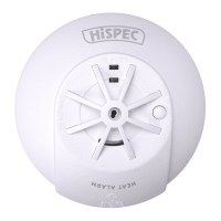
MODEL: HSSA/HE/RF10-PRO
HISPEC ELECTRICAL PRODUCTS LTD UNIT 21 CHORLEY NORTH BUSINESS PARK, CHORLEY, LANCASHIRE PR6 7BX | WWW.HISPEC.CO.UK | VERSION 092022
CLASS II APPARATUS
2792-CPR-838573
ASSOCIATE STANDARD
BS 5839-6:2019 GRADE D1
Wall Mounting
Do not mount tight into the corners. Put the top edge of your alarm between
150 and 300mm below the ceiling. Keep at least 300mm from room
corners. See Figure 3i
On a Sloping Ceiling
In areas with sloping or peaked ceilings install your alarm in accordance
with Figure 3ii because "dead air" at the apex may not allow hot air to
adequately enter the alarm.
If your dwelling is multi-story, for minimum protection one alarm should
be tted at the bottom of the staircase with further alarms tted on each
upstairs landing. This includes basements but excludes crawl spaces and
unnished attics. See Figure 2 for examples.
NOTE: For maximum protection smoke alarms should be tted in
every room (except kitchen, bathroom and garage).
POSITIONING THE HEAT ALARM
Ceiling Mounting
As hot air rises and spreads, it is advisable to mount on a ceiling in a
central position. Avoid areas where there is no air circulation. E.g. Corners
of rooms and keep away from items which may prevent the free ow of air.
Place the unit at least 300mm from any light ttings or decorative objects
which might obstruct smoke entering the alarm. Keep at least 300mm away
from walls. See Figure 3i.
AREAS TO BE AVOIDED:
• Situations where the temperature may fall below 4
°
C for extended
periods
• Humid areas such as BATHROOMS, SHOWER ROOMS where the
relative humidity may exceed 90% as vapour will cause false alarms.
• Near a DECORATIVE OBJECT, DOOR, LIGHT FITTING, WINDOW
MOULDING etc., that may prevent hot air from entering the alarm.
• In VERY DUSTY OR DIRTY environments such as workshops.
• Locate unit at least 1.5m and route wiring at least 1m away for
FLUORESCENT LIGHT FITTINGS as electrical “noise” and/or ickering
may affect the unit. Do not wire into the same circuit as uorescent lights
or dimmers.
• Do not locate in INSECT INFESTED AREAS. Insects and contamination
on the alarm sensor can increase its response time.
BS 5446-2:2003
WIRELESS CONNECTING THE ALARM
Wireless pairing the alarm, smoke alarm, or heat alarm (Learning
mode)
On First Alarm
Press Wireless Pairing Button & hold for 5 seconds
until LED lights up.
On all additional alarms
Press Wireless Pairing Button 2 times. Pairing Light will ash
RED. Repeat for each additional alarm.
IMPORTANT!
The Wireless Pairing Button is only used for wireless
interconnection.
WHEN TESTING, HOLD THE ROUND WHITE TEST BUTTON ON
THE FRONT OF THE ALARM AND ALL WIRELESSLY PAIRED
ALARMS SHOULD SOUND WITHIN 20 SECONDS.
Wireless Pairing Mode:
The Pairing Light is on for 30 seconds
Wireless Pairing Button
Pairing Light
FIGURE 2 - 2/3 STORY DWELLING
ATTIC
FIGURE 1 - SINGLE STORY DWELLING