8
English
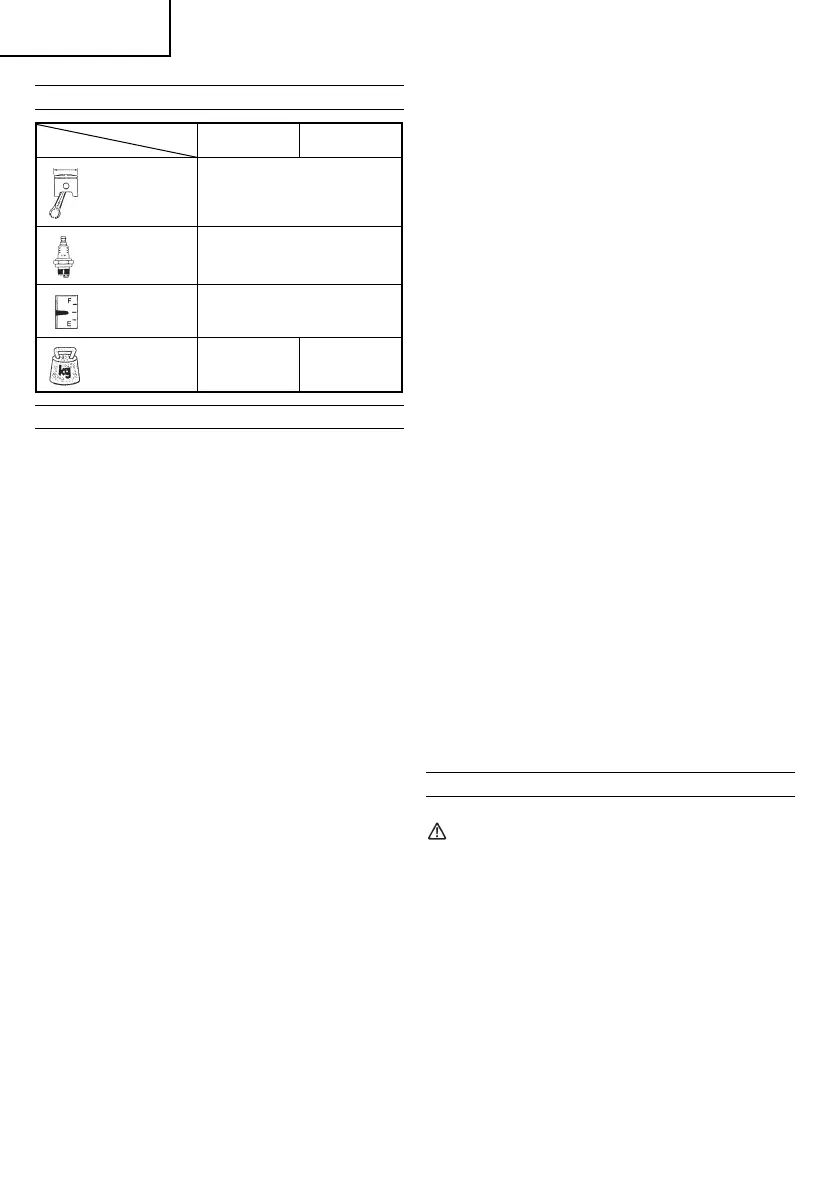
SPECIFICATIONS
MODEL
CG31EBS CG31EBS (L)
Engine
Size (ml)
30.8
Spark Plug CHAMPION RCJ6Y
Fuel Tank
Capacity (l)
0.67
Dry Weight
(kg)
6.4 5.8
ASSEMBLY PROCEDURES
Drive shaft to engine (Fig. 1)
Loosen tube locking bolt (1) about ten turns so that the
bolt point will not obstruct drive shaft tube to be inserted.
When inserting drive shaft tube, hold the tube locking bolt
outward preventing inside fi tting from obstructing as well.
NOTE
When it is hard to insert drive shaft up to the marked
position on the drive shaft tube, turn drive shaft by the
cutter mounting end clockwise or counter-clockwise.
Tighten tube locking bolt lining up the hole in the shaft
tube. Then tighten clamp bolt securely (1).
Installation of handle
Remove the handle bracket (2) from the assembly. (Fig. 2)
Place the handles and attach the handle bracket with four
bolts lightly. Adjust to appropriate position. Then fi x it fi rmly
with the bolts.
Fix protection tube on drive shaft or handle using cord
clamps (3). (Fig. 3)
NOTE
If the protection tube is set apart from the handle or pipe,
it will be caught by something during operation and it
may cause serious injury. Do not set the protection tube
apart from the handle or pipe.
Throttle wire/stop cord
Remove air cleaner cover. (Fig. 4)
Loosen and remove the screw from the throttle wire holder.
(Fig. 6)
Connect the terminals of the stop cords coming out from
the engine and shaft. (Fig. 5)
Hook the throttle wire end on the throttle of the carburetor.
Make sure that the throttle lever shown in the Fig.15 is set
at the “idle” position.
Put the throttle outer end into the groove, and then cover
it with the throttle wire holder and fi x the holder with the
screw. (Fig. 7)
Then, install the cleaner cover.
Fix the protection tube which the stop cords and throttle
wire are passing through, on the pipe with the hip pad.
Then, as shown in the fi gure, fi x the protection tube on the
pipe and handle with the bands in the bag.
After fi xing, cut off the extra part of the band not to obstruct
the operation. (Fig. 3)
NOTE
If the protection tube is set apart from the handle or
pipe, it will be caught by something during operation
and it may cause serious injury.
Do not set the protection tube apart from the handle or
pipe.
Installation of blade guard (Fig. 9)
Install the blade guard on drive shaft tube against angle
transmission (4). Tighten the guard bracket fi rmly so that
the blade guard does not swing or move down during
operation.
Install the gear case and blade guard so that blade guard
contacts the gear case. (Fig.10)
CAUTION
The blade guard must be in place when operating.
If the blade guard is not in place when operating, you
may get the serious injury.
Installation of cutting blade (Fig. 11)
When installing a cutting blade, make sure that there are no
cracks or any damage in it and that the cutting edges are
facing the correct direction.
Align the notch hole of the cutter holder with the hole on the
gear case (Top the gear case) and insert the Allen wrench
to stop turning. Turn the fi xing nut clockwise and remove
the fi xing nut, cutter holder cap, and toothed lock washers.
The installation of the cutting blade is as follows: insert the
Allen wrench into the notch hole of the cutter holder and
the hole on the gear case. Then, install the cutting blade
(check the installing direction, as referring to Fig. 13), the
cutter holder cap and toothed lock washers onto the cutter
holder in this order. Finally, tighten the fi xing nut securely
by turning counterclockwise with the Combi box spanner.
(Fig. 11)
CAUTION
○ When installing the cutting blade, set its center hole to
the convex part of the cutter holder and hold it with the
concave surface of the cutter holder cap. Then, tighten
the fi xing nut to prevent the cutting blade from being
eccentric. (Fig. 12)
After installing the cutting blade, be sure to remove the
Allen wrench and Combi box spanner.
○ Before operation, make sure the blade has been
properly installed.
○ Cutter holder cap under a cutting blade, check it for
wear or cracks before operation. If any damage or wear
is found, replace it, as it is an article of consumption.
NOTE
The blade must be retained with a new cotter pin each
time installed. (Fig. 11)
OPERATING PROCEDURES
Fuel (Fig. 14)
WARNING
○ The Brush cutter is equipped with a two-stroke engine.
Always run the engine on fuel, which is mixed with oil.
Provide good ventilation, when fueling or handling fuel.
○ Fuel contains highly fl ammable and it is possible to get
the serious personal injury when inhaling or spilling on
your body. Always pay attention when handling fuel.
Always have good ventilation when handling fuel inside
building.
Fuel
○ Always use branded 89 octane unleaded gasoline.
○ Use genuine two-cycle oil or use a mix between 25:1
to 50:1, please consult the oil bottle for the ratio or
HITACHI dealer.
○ If genuine oil is not available, use an anti-oxidant added
quality oil expressly labeled for air-cooled 2-cycle
engine use (JASO FC GRADE OIL or ISO EGC GRADE).
Do not use BIA or TCW (2-stroke water-cooling type)
mixed oil.
000BookCG31EBSTha.indb8000BookCG31EBSTha.indb8 2009/06/3016:29:122009/06/3016:29:12
 Loading...