SAFETY PRECAUTION
●
Read the safety precautions carefully before operating the unit.
●
The contents of this section are vital to ensure safety. Please pay special attention to the following sign.
WARNING ........ Incorrect methods of installation may cause death or serious injury.
CAUTION ......... Improper installation may result in serious consequence.
Make sure to connect earth wire.
This sign in the gures indicates prohibition.
Be sure that the unit operates in proper condition after installation. Explain to customer the proper operation
and maintenance of the unit as described in the user’s guide. Ask a customer to keep this installation manual
together with the instruction manual.
Tools Needed For Installation Work
!
●
Carefully read through the procedures of
proper installation before starting installation
work.
●
The sales agent should inform customers
regarding the correct operation of installation.
(Mark
is exclusive use tool for R32)
●
+
–
Screwdriver
●
Measuring Tape
●
Knife
●
Saw
●
ø 65mm Power Drill
●
Hexagonal Wrench Key ( 4mm)
●
Wrench (14,17,19,22mm)
Gas Leakage Detector
●
Pipe Cutter
●
Putty
●
Vinyl Tape
●
Pliers
●
Flare Tool Vacuum Pump Adaptor
Manifold Valve Charge Hose
Vacuum Pump
●
Please request your sales agent or quali ed technician to install your unit. Water leakage,
short circuit or re may occur if you do the installation work yourself.
●
Please observe the instructions stated in the installation manual during the process of
installation. Improper installation may cause water leakage, electric shock and re.
●
Make sure that the units are mounted at locations which are able to provide full support to
the weight of the units. If not, the units may collapse and impose danger.
●
Observe the rules and regulations of the electrical installation and the methods described in
the installation manual when dealing with the electrical work. Use cables which are of cially
approved in your country. Be sure to use the speci ed circuit. A short circuit and re may
occur due to the use of low quality wire or improper work.
●
Be sure to use the speci ed cables for connecting the indoor and outdoor units. Please
ensure that the connections are tight after the conductors of the wire are inserted into the
terminals to prevent the external force is being applied to the connection section of the
terminal base. Improper insertion and loose contact may cause over-heating and re.
●
Please use the speci ed components for installation work. Otherwise, the units may collapse
or water leakage, electric shock, re or stronger vibration may occur.
●
Be sure to use the speci ed piping set for R32. Otherwise, this may result in broken copper
pipes or faults.
●
When installing or transferring an air conditioner to another location, make sure that air
other than the speci ed refrigerant(R32) does not enter the refrigeration cycle. If other air
should enter, the pressure level of the refrigeration cycle may increase abnormally which
could result in a rupture and injury.
●
Be sure to ventilate fully if a refrigerant gas leak while at work. If the refrigerant gas comes
into contact with re, a poisonous gas may occur.
●
After completion of installation work, check to make sure that there is no refrigeration gas
leakage. If the refrigerant gas leaks into the room, coming into contact with re in the fan-
driven heater, space heater, etc., a poisonous gas may occur.
●
Unauthorized modi cations to the air conditioner may be dangerous. If a breakdown occurs
please call a quali ed air conditioner technician or electrician. Improper repairs may result
in water leakage, electric shock and re, etc.
●
Be sure to connect the earth line from the power supply wire to the outdoor unit and between
the outdoor and indoor unit. Do not connect the earth line to the gas tube, water pipe, lighting
rod or the earth line of the telephone unit. Improper earthing may cause electric shocks.
●
When nishing the refrigerant collection (pumping down), stop the compressor and then
remove the coolant pipe. If you remove the refrigerant pipe while the compressor is operating
and the service valve is released, air is sucked and a pressure in the freezing cycle system
will build up steeply, causing an explosion or injury.
●
When installing the unit, be sure to install the refrigerant pipe before starting the compressor.
If the refrigerant pipe is not installed and the compressor is operated with the service
valve released, air is sucked and the pressure level of the refrigeration cycle may increase
abnormally which could result in a rupture and injury.
●
The electric cables should neither be reworked nor added. Make sure to use an exclusive
circuit breaker. Otherwise re or electric shock might occur by connection failure, isolation
failure or over current.
●
Make sure to connect cables to terminal properly and terminal cover should close rmly.
Otherwise, over heating at terminal contact, re or electric shock might occur.
●
Make sure that there is no dust on any connected points of electric cables and x rmly.
Otherwise, re or electric shock might occur.
CAUTION
!
●
A circuit breaker must be installed in the house distribution
box for the direct connected power supply cables to the
outdoor unit. In case of other installations a main switch
with a contact gap or more than 3mm has to be installed.
Without a circuit breaker, the danger of electric shock
exists..
●
Do not install the unit near a location where
there is ammable gas. The outdoor unit may
catch re if ammable gas leaks around it.
●
Please ensure smooth ow of water when installing the
drain hose. Improper installing may wet your furniture.
●
An IEC approved power cord should be used. Power cord
type: NYM.
WARNING
●
The unit should be mounted at stable, non-vibratory location which can provide full support to the unit.
CAUTION
●
No nearby heat source and no obstruction near the air outlet is allowed.
●
The clearance distances from top, right and left are speci ed in gure below.
●
The location must be convenient for water drainage and pipe connection with the Outdoor unit.
●
No nearby leakage risk of ammable gas, and no nearby source of vapor or oil smoke.
●
To avoid interference from noise, please place the unit and its remote controller at least 1m from the radio and television.
●
To avoid any error in signal transmission from the remote controller, please put the controller far away from high-frequency
machines and high-power wireless systems.
●
The installation height should be at least 2300 mm or more from the oor.
●
The distance from the air outlet to the re alarm must be at least 1500mm and there must be no re alarm in the front
direction of the indoor unit.
The Choice of Mounting Site (Please note the following matters and obtain permission from customer before installation).
WARNING
CAUTION
CAUTION
CAUTION
This symbol shows that this equipment uses a ammable
refrigerant.
If the refrigerant is leaked, together with an external ignition
source, there is a possibility of ignition.
This symbol shows that the Operation Instructions should
be read carefully.
This symbol shows that a service personnel should be
handling this equipment with reference to the Installation
Manual.
This symbol shows that there is information included in
the Operation Manual and/or Installation Manual.
Direction of Piping
There are 6 directions
allowed, namely,
backward piping,
backward piping from left,
horizontally piping from
right, horizontally piping
from left, vertically down
from right, vertically down
from left.
Backward piping from left
Connection
above 50mm
about 450mm
2300 or more
above 100mm
above 100mm
must not bend
about 300mm
Be sure to
completely
seal any gap
with putty.
The indoor piping should be
insulated with the enclosed
insulation pipe. (If the insulator
is insufficient, please use
commercial products.)
Installation of Hanger, Wall Penetration and Installation of Protection Pipe
1
CAUTION
!
●
The draining of the water container inside the indoor unit can be done from the left. Therefore the hanger
must be xed horizontally or slightly tilted towards the side of drain hose. Otherwise, condensed water
may over ow the water container.
Direct Mounting On The Wall
●
Please use hidden beams in the wall to hold the hanger.
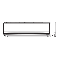
INDOOR UNIT
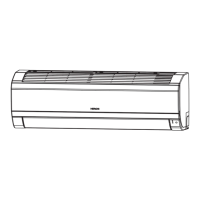
Figure showing the Installation of Indoor Unit.
Level
Line
Weight
Wall hole
Screw for Hanger
Hanger
Screw the hanger at the positions
possibly near the upper and lower
hooks where the indoor unit is
hung. Use 4 or more screws to
x the hanger.
Installation of the Indoor Unit
2
Cutting Low Cover bush
1 PIPING FROM THE RIGHT SIDE (BACKWARD, DOWNWARD, HORIZONTAL)
● While installing the pipe from the right, left or bottom
side, use a knife to cut openings as shown in gure.
Then smoothen the edges of openings with a le.
Openings
Openings
Preparation
Connecting cords, pipe
and drain hose must
be laid together with
Vinyl tape.
● Connect connecting cord.
● Pull out the pipe, connecting cord and drain hose.
Installation
● Insert the pipe through the wall hole.
1 The upper part of the Indoor unit is hanged on the hanger.
2
The projection at the lower part of the Indoor unit is hooked
onto the hanger
Wall hole
Pipe
Drain hose
Drain layout of backward piping
Cable
Hanger
Refrigerating
pipe
Lift the body of
the unit upwards
and then force it
downwards.
Protection Pipe
Drain Hose
Connecting Cord
Hanger
Projection
2 PIPING FROM THE LEFT SIDE (BACKWARD, DOWNWARD, HORIZONTAL)
Preparation
Changed of Drain Hose and Installation Procedures
● Exchange the location of drain hose and drain cap while installing the pipe from the left side as shown in below.
Be sure to plug in the drain hose until the insulating material folds upon itself.
● Please use pliers to pull out the drain cap.
(This is an easier way to remove the drain
cap).
Insuf cient insert may result in water leakage.
!
CAUTION
Pipe
Pipe support
Rubber strap tied
with great force
Transform after
bending downward
1
1
2
1
!
CAUTION
INSTALLATION
MANUAL
<
SIA2377: A
>
Home
800
!
!
42.5mm
Drain Hose
Be sure that the wire is not in contact with any metal in the wall. Please use the protection pipe as wire passing
through the hollow part of the wall so as to prevent the possibility of damaged by mouse. Unless it seals
completely, any air with high humidity flows from outdoor and dew may drop.
Indoor Outdoor
Wall Penetration and Installation of Protection Pipe
●
Drill a ø 65mm hole on wall which is slightly tilted towards the outdoor side.
Drill the wall at a small angle.
Cut the protection pipe according to the wall thickness.
Seal with
Seal with
putty
putty
2-5mm
●
Protection
pipe
Sleeve of
protection pipe
!
WARNING
Installation Of Remote Controller
●
The remote controller can be placed in its
holder which is fixed on wall or beam.
To operate the remote controller at its holder,
please ensure that the unit can receive signal
transmitted from the controller at the place
where the holder is to be fixed.The unit will
beep when signal is received from the remote
controller. The signal transmission is weaken
by the fluorescent light. Therefore, during the
installation of the remote control holder, please
switch on the light, even during day time, to
determine the mounting location of the holder.
●
4
Plug
How to select 1.8kw or 1.2kw
capacity for RAK-XJ18QHAE
5
8
Remote controller setting to
select 1.8kw or 1.2kw capacity,
please refer to the service
manual for detailed introduction.
3
Names of Indoor Components
No. Item Qty
Hanger
1
1
Screw for Hanger
2
6
AAA
size Battery
3
2
Remote Controller
4
1
Screw for Remote
5
Controller Holder
2
Air purifying filter
6
2
C-case
7
2
Remote Controller Holder
8
1
Insulation
sheet
Drain cap
● Remove low cover.
● Insert drain cap up to
the location securely
till the cap stops.
●
Push the pipe deeply
until the insulating
section of the drain
hose end gets over
the rib at the indoor
unit side.
Drain HoseDrain cap
Empty gap in the sleeve of protection pipe should be completely sealed with putty to avoid dripping of rain water
into the room.
Please ensure smooth flow of water when installing the drain hose. Improper installing may wet your furniture.
●
●
●
An IEC approved power cord should be used. Power cord type: NYM.
The remote controller must be slide in
the remote controller holder, in the
direction as shown in the figure, until
it hooks at the lower end of the remote
controller holder.
Remote
Controller
Remote
Controller
Holder
Screw (2 pieces)
Procedures of Installation and Precautions
1. 3. Fix the hanger on wall
●
Procedures to fix the hanger.
Drill holes on wall.
(As shown below)
2. Push plug into the holes.
(As shown below)
with 4.1 x 32 screw
(As shown in figure below)
Wall
32mm
ø4.8mm
1
2
Hanger
Plug
Wall
(From commercial
product)
Screw
Wall
8
Remote
Control
Holder
20mm
5
Screw
Plug (From commercial product)
ø4.4mm
Procedures to fix the holder of remote control.
1.
Drill holes on wall.(As shown below)
2.Push plug into the holes.
(As shown below)
● The rubber strap used for fixing the insulator should not be tied with great force.
Otherwise, this will damage heat insulation and causes water condensation.
● Please pull the lower part of the indoor unit outwards to check if the unit is hooked
onto the hanger. Improper installation may cause vibration and noise.
● T ransform the piping while holding down the lower portion of pipe-support by
hand.
Ceiling
WALL
<SIA2377: A >
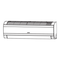
SPLIT UNIT AIR CONDITIONER
INDOOR UNIT
RAK-XJ18QHAE
RAK-XJ25RHAE
RAK-XJ35RHAE
RAK-XJ50RHAE
EN INSTRUCTION MANUAL
FOR SERVICE
PERSONNEL ONLY
!
Cooling & Heating
WARNING
This symbol shows that this equipment uses a ammable
refrigerant.
If the refrigerant is leaked, together with an external
ignition source, there is a possibility of ignition.
CAUTION
This symbol shows that the Operation Instructions should
be read carefully.
CAUTION
This symbol shows that a service personnel should be
handling this equipment with reference to the Installation
Manual.
CAUTION
This symbol shows that there is information included in
the Operation Manual and/or Installation Manual.
No.
Item
Qty
Hanger
1
Screw for Hanger
6
AAA size Battery
2
Remote Controller
1
5
Screw for Remote
Controller Holder
2
6
Air purifying lter
2
7
C-case
2
8
Remote Controller Holder
1
INSTALLATION
MANUAL
SPLIT UNIT AIR CONDITIONER
INDOOR UNIT
RAK-XJ18QHAE
RAK-XJ25RHAE
RAK-XJ35RHAE
RAK-XJ50RHAE
EN
INSTRUCTION MANUAL
FOR SERVICE
PERSONNEL ONLY
● Carefully read through the procedures of
proper installation before starting installation
work.
● The sales agent should inform customers
regarding the correct operation of installation.
Tools Needed For Installation Work
(Mark is exclusive use tool for R32)
● Screwdriver ● Measuring Tape
● Knife ● Saw ● ø 65mm Power Drill
● Hexagonal Wrench Key ( 4mm)
● Wrench (14,17,19,22mm) Gas Leakage
Detector ● Pipe Cutter ● Putty ● Vinyl Tape
● Pliers ● Flare Tool Vacuum Pump
Adaptor Manifold Valve Charge Hose
Vacuum Pump
WARNING
● Please request your sales agent or qualied technician to install your unit. Water leakage, short
circuit or re may occur if you do the installation work yourself.
● Please observe the instructions stated in the installation manual during the process of installation.
Improper installation may cause water leakage, electric shock and re.
● Make sure that the units are mounted at locations which are able to provide full support to the weight
of the units. If not, the units may collapse and impose danger.
● Observe the rules and regulations of the electrical installation and the methods described in the
installation manual when dealing with the electrical work. Use cables which are ocially approved in
your country. Be sure to use the specied circuit. A short circuit and re may occur due to the use of
low quality wire or improper work.
● Be sure to use the specied cables for connecting the indoor and outdoor units. Please ensure that
the connections are tight after the conductors of the wire are inserted into the terminals to prevent
the external force is being applied to the connection section of the terminal base. Improper insertion
and loose contact may cause over-heating and re.
● Please use the specied components for installation work. Otherwise, the units may collapse or
water leakage, electric shock, re or stronger vibration may occur.
● Be sure to use the specied piping set for R32. Otherwise, this may result in broken copper pipes or
faults.
● When installing or transferring an air conditioner to another location, make sure that air other than
the specied refrigerant(R32) does not enter the refrigeration cycle. If other air should enter, the
pressure level of the refrigeration cycle may increase abnormally which could result in a rupture and
injury.
● Be sure to ventilate fully if a refrigerant gas leak while at work. If the refrigerant gas comes into
contact with re, a poisonous gas may occur.
● After completion of installation work, check to make sure that there is no refrigeration gas leakage.
If the refrigerant gas leaks into the room, coming into contact with re in the fandriven heater, space
heater, etc., a poisonous gas may occur.
● Unauthorized modications to the air conditioner may be dangerous. If a breakdown occurs please
call a qualied air conditioner technician or electrician. Improper repairs may result in water leakage,
electric shock and re, etc.
● Be sure to connect the earth line from the power supply wire to the outdoor unit and between the
outdoor and indoor unit. Do not connect the earth line to the gas tube, water pipe, lighting rod or the
earth line of the telephone unit. Improper earthing may cause electric shocks.
● When nishing the refrigerant collection (pumping down), stop the compressor and then remove the
coolant pipe. If you remove the refrigerant pipe while the compressor is operating and the service
valve is released, air is sucked and a pressure in the freezing cycle system will build up steeply,
causing an explosion or injury.
● When installing the unit, be sure to install the refrigerant pipe before starting the compressor. If the
refrigerant pipe is not installed and the compressor is operated with the service valve released, air is
sucked and the pressure level of the refrigeration cycle may increase abnormally which could result
in a rupture and injury.
● The electric cables should neither be reworked nor added. Make sure to use an exclusive circuit
breaker. Otherwise re or electric shock might occur by connection failure, isolation failure or over
current.
● Make sure to connect cables to terminal properly and terminal cover should close rmly.
Otherwise, over heating at terminal contact, re or electric shock might occur.
● Make sure that there is no dust on any connected points of electric cables and x rmly. Otherwise,
re or electric shock might occur.
SAFETY PRECAUTION
● Read the safety precautions carefully before operating the unit.
● The contents of this section are vital to ensure safety. Please pay special attention to the following sign.
Be sure that the unit operates in proper condition after installation. Explain to customer the proper operation
and maintenance of the unit as described in the user’s guide. Ask a customer to keep this installation manual
together with the instruction manual.
Access the full version of the
User Installation Manual by
scanning the code.
WARNING ...... Incorrect methods of installation may cause death or serious injury.
CAUTION ....... Improper installation may result in serious consequence.
Make sure to connect earth wire.
This sign in the gures indicates prohibition.
The Choice of Mounting Site
(Please note the following matters and obtain permission from customer before installation).
● A circuit breaker must be installed in the house distribution
box for the direct connected power supply cables to the
outdoor unit. In case of other installations a main switch
with a contact gap or more than 3mm has to be installed.
Without a circuit breaker, the danger of electric shock
exists.
● Do not install the unit near a location where
there is ammable gas. The outdoor unit may
catch re if ammable gas leaks around it.
● Please ensure smooth ow of water when installing the
drain hose. Improper installing may wet your furniture.
● An IEC approved power cord should be used. Power cord
type: NYM.
!
CAUTION
!
WARNING
● The unit should be mounted at stable, non-vibratory location which can provide full support to the unit.
!
CAUTION
● No nearby heat source and no obstruction near the air outlet is allowed.
● The clearance distances from top, right and left are specied in gure below.
● The location must be convenient for water drainage and pipe connection with the Outdoor unit.
● No nearby leakage risk of ammable gas, and no nearby source of vapor or oil smoke.
● To avoid interference from noise, please place the unit and its remote controller at least 1m from the radio and television.
● To avoid any error in signal transmission from the remote controller, please put the controller far away from high-frequency
machines and high-power wireless systems.
● The installation height should be at least 2300 mm or more from the oor.
● The distance from the air outlet to the re alarm must be at least 1500mm and there must be no re alarm in the front direction
of the indoor unit.
Figure showing the Installation of Indoor Unit.
Be sure to
completely
seal any gap
with putty.
The indoor piping should be
insulated with the enclosed
insulation pipe. (If the insulator
is insucient, please use
commercial products.)
Screw the hanger at the positions
possibly near the upper and
lower hooks where the indoor unit
is hung. Use 4 or more screws to
x the hanger.
Direction of Piping
Backward piping from left
Connection
There are 6 directions
allowed, namely,
backward piping,
backward piping from left,
horizontally piping from
right, horizontally piping
from left, vertically down
from right, vertically down
from left.
above 50mm
above 100mm
above 100mm
Names of Indoor Components
about 450mm
about 300mm
must not bend
Insulation
sheet
Plug
2300 or more
How to select 1.8kw or 1.2kw
capacity for RAK-XJ18QHAE
Remote controller setting to
select 1.8kw or 1.2kw capacity,
please refer to the service
manual for detailed introduction.
INDOOR UNIT
Installation of Hanger, Wall Penetration and Installation of Protection Pipe
!
CAUTION
● The draining of the water container inside the indoor unit can be done from the left. Therefore the hanger
must be xed horizontally or slightly tilted towards the side of drain hose. Otherwise, condensed water may
overow the water container.
!
WARNING
Be sure that the wire is not in contact with any metal in the wall. Please use the protection pipe as wire passing
through the hollow part of the wall so as to prevent the possibility of damaged by mouse. Unless it seals
completely, any air with high humidity ows from outdoor and dew may drop.
Direct Mounting On The Wall
● Please use hidden beams in the wall to hold the hanger.
Cutting Low Cover bush
● While installing the pipe from the right, left or bottom
side, use a knife to cut openings as shown in gure.
Then smoothen the edges of openings with a le.
Procedures of Installation and Precautions
● Procedures to x the hanger.
Installation Of Remote Controller
●
The remote controller can be placed in its
holder which is xed on wall or beam.
●
To operate the remote controller at its holder,
please ensure that the unit can receive signal
transmitted from the controller at the place
where the holder is to be xed.The unit will
beep when signal is received from the remote
controller. The signal transmission is weaken
by the uorescent light. Therefore, during the
installation of the remote control holder, please
switch on the light, even during day time, to
determine the mounting location of the holder.
● Push the pipe deeply
until the insulating
section of the drain
hose end gets over
the rib at the indoor
unit side.
● Remove low cover.
● Insert drain cap up to
the location securely
till the cap stops.
Drain cap
Drain cap
Drain Hose
Wall Penetration and Installation of Protection Pipe
● Drill a ø 65mm hole on wall which is slightly tilted towards the outdoor side.
Drill the wall at a small angle.
● Cut the protection pipe according to the wall thickness.
1. Drill holes on wall.
(As shown below)
2. Push plug into the holes.
(As shown below)
The remote controller must be slide
in the remote controller holder, in the
direction as shown in the gure, until it
hooks at the lower end of the remote
controller holder.
2. Push plug into the holes.
(As shown below)
3. Fix the hanger on wall with
4.1 x 32 screw
(As shown in gure below)
Visible outline of
the indoor unit
660mm
15mm
115mm
42.5mm
294mm
36mm
67mm
950mm
20mm
Drain Hose
Screw for Hanger
Hanger
Wall hole
Weight
Line
Level
Ø65
Ø65
105mm
145mm 145mm
ø4.8mmø4.4mm
● Procedures to x the holder of remote control.
1.Drill holes on wall.(As shown below)
32mm
Hanger
Ceiling
Openings
Openings
Screw
Wall
Plug
(From commercial
product)
Wall
Wall
8
Remote
Control
Holder
Screw
Plug
(From commercial product)
<SIA2377: >
Indoor
Outdoor
Seal with
putty
Seal with
putty
2-5mm
Protection
pipe
WALL
Sleeve of
protection pipe
Remote
Controller
Remote
Controller
Holder
Screw (2 pieces)
● Empty gap in the sleeve of protection pipe should be completely sealed with putty to avoid dripping of rain water into
the room.
● Please ensure smooth ow of water when installing the drain hose. Improper installing may wet your furniture.
● An IEC approved power cord should be used. Power cord type: NYM.
Installation of the Indoor Unit
PIPING FROM THE RIGHT SIDE (BACKWARD, DOWNWARD, HORIZONTAL)
PIPING FROM THE LEFT SIDE (BACKWARD, DOWNWARD, HORIZONTAL)
Preparation
● Connect connecting cord.
● Pull out the pipe, connecting cord and drain hose.
Installation
● Insert the pipe through the wall hole.
The upper part of the Indoor unit is hanged on the hanger.
The projection at the lower part of the Indoor unit is hooked
onto the hanger
Preparation
Changed of Drain Hose and Installation Procedures
● Exchange the location of drain hose and drain cap while installing the pipe from the left side as shown in below.
Be sure to plug in the drain hose until the insulating material folds upon itself.
Connecting cords, pipe
and drain hose must be
laid together with Vinyl
tape.
Hanger
Hanger
Protection Pipe
Refrigerating
pipe
Lift the body of
the unit upwards
and then force it
downwards.
Connecting Cord
Projection
Wall hole
Drain layout of backward piping
Pipe
Drain hose
Cable
Drain Hose
!
CAUTION
Insufcient insert may result in water leakage.
● Please use pliers to pull out the drain cap.
(This is an easier way to remove the drain
cap).
!
CAUTION
● The rubber strap used for xing the insulator should not be tied with great force.
Otherwise, this will damage heat insulation and causes water condensation.
● Please pull the lower part of the indoor unit outwards to check if the unit is
hooked onto the hanger. Improper installation may cause vibration and noise.
● Transform the piping while holding down the lower portion of pipe-support by
hand.
Pipe support
Rubber strap tied
with great force
Transform after
bending downward
Pipe