·E99
2.
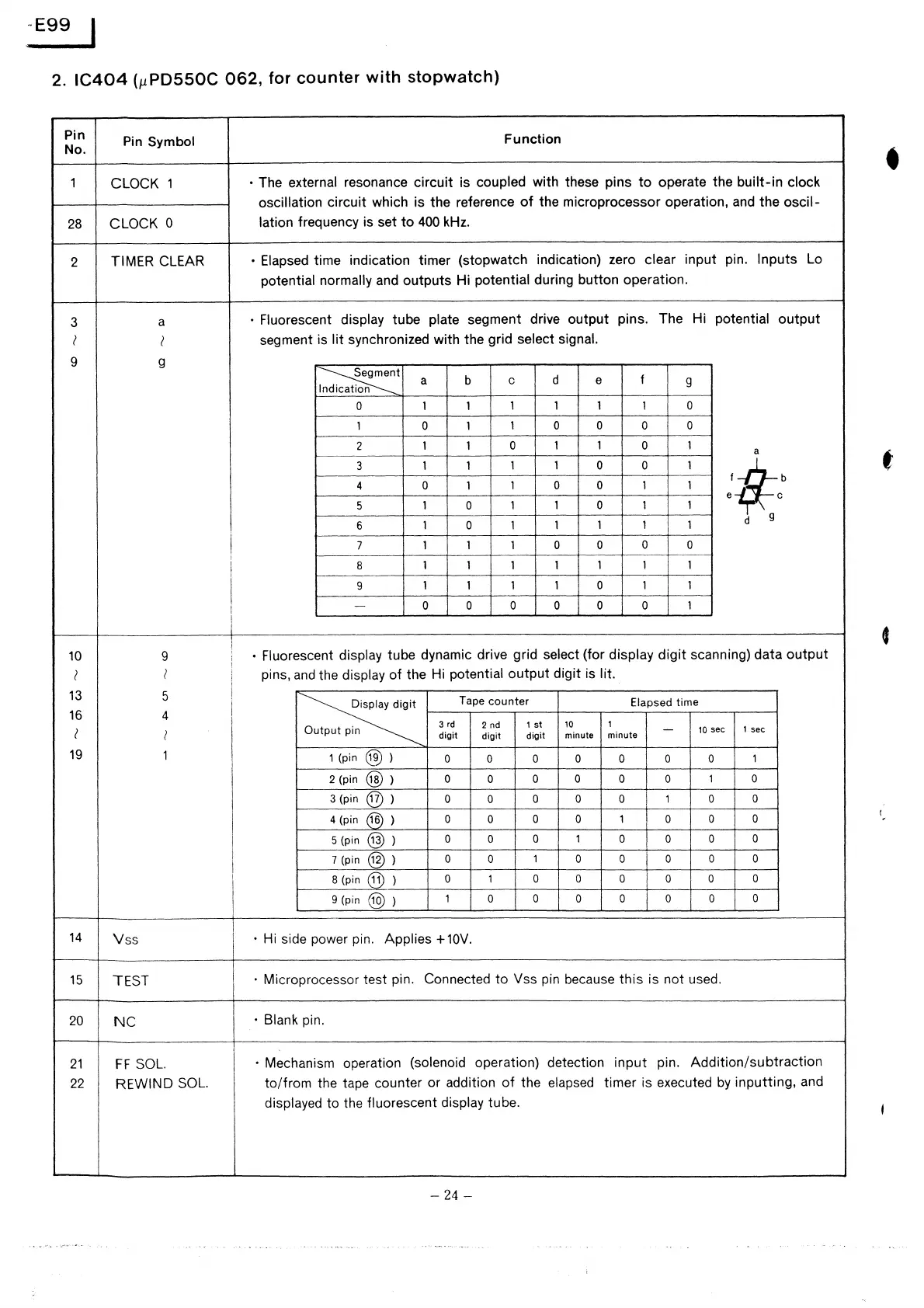
IC404
(µPDSSOC
062,
for
counter
with
stopwatch)
Pin
Pin
Symbol
Function
No.
•
1
CLOCK 1
• The external resonance circuit is coupled with these pins
to
operate the built-in clock
oscillation
circuit which is the reference
of
the microprocessor operation,
and
the oscil-
28
CLOCK 0
lation
frequency is set
to
400
kHz.
2
TIMER CLEAR
•
Elapsed
time indication timer (stopwatch indication) zero clear input
pin.
Inputs
Lo
potential normally
and
outputs Hi potential during button operation.
3
a
• Fluorescent display tube plate segment drive output
pins.
The Hi
potential output
l
l
segment is
lit
synchronized with the grid select signal.
9
g
~t
b
d
f
I c o
a
c e
9
0 1 1
1 1 1 1
0
1 0 1
1
0 0
0
0
2
1
1
0 1
1
0
1
a
3
1 1
1 1
0 0 1
4
0
1
1
0 0 1
1
'$t
e c
5
1
0
1 1 0 1
1
6
1 0 1
1 1 1 1
d g
t
7
1 1 1
0 0
0
0
8
1 1 1 1
1 1 1
9
1 1 1 1 0
1 1
-
0 0 0 0 0 0 1
•
10
9
• Fluorescent display tube dynamic drive grid select (for display digit scanning) data output
I
I
pins,
and
the display
of
the Hi potential output digit is lit.
13
5
~
Tape
counter
Elapsed time
16
4
3
rd
2 nd
1
st
10
1
-
10
sec
1
sec
l
I
n
digit
digit
digit
minute
minute
19
1
1(pin@)
0 0 0 0 0 0 0
1
2(pin@)
0
0
0 0 0
0
1
0
3(pin@)
0
0
0 0 0 1 0
0
4 (pin
(i6)
)
0 0 0 0
1
0
0 0
5 (pin
@)
)
0
0
0 1 0 0 0
0
7(pin@)
0 0
1
0 0 0
0 0
B(pin@)
0 1 0 0 0 0 0
0
9 (pin
@)
}
1 0 0 0 0 0 0
0
14
Vss
• Hi side power pin. Applies +
10V.
15
TEST
•
Microprocessor test pin.
Connected to Vss pin because this is not used.
20
NC
·Blank
pin.
21
FF
SOL.
• Mechanism operation (solenoid operation) detection
input pin.
Addition/subtraction
22
REWIND
SOL.
to/from the tape counter or addition
of
the
elapsed
timer is executed
by
inputting, and
displayed to the fluorescent display tube.
- 24 -
 Loading...