44
5. INSTALLING AND PIPING [Piping the Air Compressor]
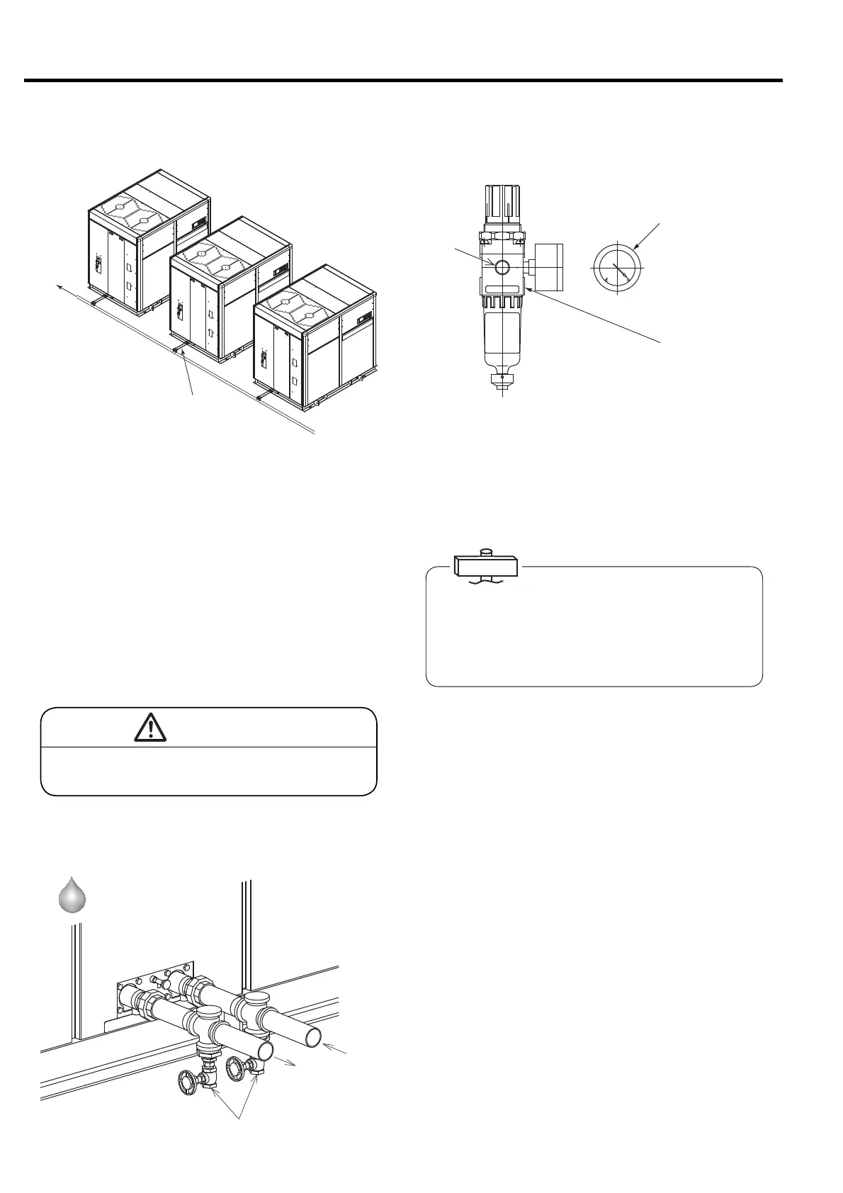
Water
Inlet
Water
outlet
Cooling drain discharge valve
① Leave the end of any condensate drain line open.
② Do not merge the air compressor’s condensate drain
lines (for the aftercooler, intercooler, control line
filter) into one common piping. Do not merge any
condensate drain line into an external condensate
drain line (for example, do not merge an air
compressor condensate drain line with a condensate
drain line on an air receiver tank). This could
generate a pressure differential, which could result
in no draining or inconsistent draining out of the air
compressor. Capability to observe the draining of
the air compressor is also impaired.
5.4.6 Drain Pipe
To drain
pit
Drain Pipe
Pressure gauge
Filter regulator
The control air must be as dry as possible. Run the
control air pipe from the downstream side of the air dryer.
If an air dryer is not used, run the control air pipe from the
upper section of an air receiver. Installing downstream of
the air dryer or air receiver allows for less moisture
accumulation in the filter bowl of the oil mist remover.
5.4.8 OMR Control Air Piping
CAUTION
Un-drained condensate can backflow to the
air compressor and cause a failure.
5.4.7 Cooling water piping
① The pipings for water inlet and outlet for coolers are
required.
② Mount the water drain valves of the cooling water
outlet and inlet downward facing downward as
shown in the figure. The water drain valves may
also be mounted facing sideways.
③ Using flange joint to connect the air compressor to
the water pipings, allows for minimal disassembly of
the enclosure panels.
IMPORTANT
The Oil Mist Remover needs the pressure of a control
air at the regulator setting value or more. To properly
install the control air line, connect the control air pipe
to the connection marked “A” on the filter/regulator of
the Oil Mist Remover. This piping and compressed air
shall be supplied by customer.
Water-Cooled
 Loading...