46
5. INSTALLING AND PIPING [Ventilation of Air Compressor Room]
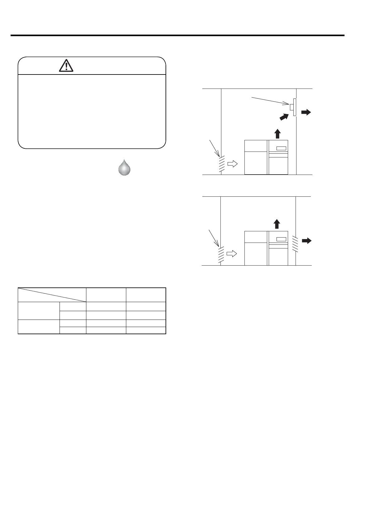
① For the small air compressor room installation,
install a ventilating fan and an air intake opening.
The position of the ventilating fan is as high as
possible and the position of the air intake opening is
as low as possible on the wall.
Select a ventilating fan with required capacity
specified in the table or higher (Fig. A). Also ensure
that the flow rate at the air intake opening is 2 m/s
or lower.
Technical Data for Room Ventilation
Model
Item/Unit
DSP-90W6N
DSP-90VW6N
DSP-110W6N
DSP-110VW6N
Heat
Generation
KBTU 46 53
(MJ/h) (49) (56)
Recommended
fan capacity ①
cfm 4,590 5,300
(m
3
/min) (130) (150)
The specified capacity is based on the allowable room
temperature rise of 9°F (5℃) and static pressure is zero0 psi
(0 MPa).
② For the factory installation with enough ventilation
capacity, select a well ventilated area (Fig. B).
Ventilating
fan
See “Recommended
fan capacity” in the
table.
Air inlet
Air inlet
Exhaust air
Exhaust air
Fresh
air
Fig. A
Fig. B
Exhaust air
Exhaust air
Fresh
air
5.5.2 Water-Cooled Type
Water-Cooled
CAUTION
When installing exhaust ducts, install a single
duct for each compressor. Alternatively, when
installing a collecting duct for multiple
compressors, install it as shown in Fig. C.
Also, be sure to install a ventilating fan with a
capacity of the value of "exhaust air from the
compressor x quantity" or more on the other
end of the duct.
 Loading...