Do you have a question about the Hitachi DV-PF3A(S) and is the answer not in the manual?
Safety precautions for laser beam operation and handling.
Notice regarding product safety characteristics and replacement parts.
Safety measures and precautions to follow during servicing procedures.
Procedures for safety checks after repair work is completed.
Detailed steps for removing and installing flat pack ICs using different methods.
Guidelines for handling semiconductors to prevent electrostatic discharge.
General notes and warnings for using the service manual.
Technical specifications for the DVD player and VCR.
Comparison of VCR features between DV-PF3A(S) and VT-FX695EGK.
Comparison of DVD features between DV-PF3A(S) and DV-P388A(S).
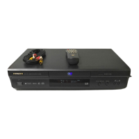
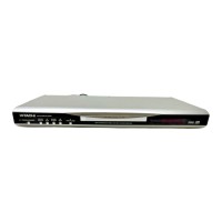
Description of controls and indicators on the front panel.
Troubleshooting guide for identifying and resolving malfunctions.
Troubleshooting flowcharts for power supply related issues.
Troubleshooting flowcharts for DVD section malfunctions.
Procedures for updating the device firmware.
Step-by-step guide to update the firmware version.
Instructions to check the current firmware version.
Periodic maintenance schedule for various components.
Procedures for cleaning video and ACE heads.
Instructions and flowchart for disassembling the unit's cabinet.
Flowchart detailing the cabinet disassembly steps.
Detailed steps for removing specific parts during cabinet disassembly.
Step-by-step procedures for disassembling and assembling the deck mechanism.
Procedures for aligning various gears and levers in the deck mechanism.
Preparation steps and cautions for entering service mode.
Guide on how to access the service mode for adjustments.
Lists required fixtures and tapes for performing adjustments.
Explains how to use the specified fixtures and alignment tape.
General notes and test equipment required for electrical adjustments.
Lists the necessary test equipment for electrical adjustments.
Procedure to adjust the head switching point for optimal playback.
Explanation of procedures for tape alignment and mechanism adjustments.
Steps to align the tape path for proper tape interchangeability.
Checks and adjustments for tape path stability and creasing.
Procedure to align the horizontal position of the audio/control/erase head.
Steps to check and adjust the envelope waveform for tracking precision.
Procedure to align the audio/control/erase head for proper tape track adherence.
Visual diagrams showing the exploded views of the unit's components.
Exploded view of the cabinet and its main assemblies.
Exploded view of the deck mechanism, section 1.
Exploded view of the deck mechanism, section 2.
Exploded view of the deck mechanism, section 3.
List of replacement mechanical parts with their part numbers.
List of replacement electrical components with their part numbers.
Wiring diagrams for different sections of the unit.
Schematic diagrams for various circuit blocks.
Display of various signal waveforms for troubleshooting.
Diagrams showing the layout of circuit boards.
Block diagrams illustrating the functional units of the device.
Timing chart related to Load/Unload switch positions.
Timing chart for still and slow playback control.
Timing chart for a sequence of VCR operations.
Timing chart for another sequence of VCR operations.
Timing chart for DVD tray and drive operations.
Pinout and function descriptions for IC501.
| Type | DVD Player |
|---|---|
| Progressive Scan | Yes |
| Remote Control | Yes |
| Video Output | Composite, S-Video, Component |
| Media Type | CD, DVD |
| Video Output System | NTSC |
| Disc Compatibility | DVD-Video, DVD-R, DVD-RW, CD-R, CD-RW |
| Audio Output | Coaxial |