UNIT INSTALLATION
PMML0293A rev.2 - 08/2016
8
6.4 THERMISTOR INSTALLATION
Liquid and gas pipes thermistors
Two type thermistors are supplied inside the control box. The
purpose and identication of each one is as follow:
Item
PCB socket
/ Thermistor
connector color
PCB
socket
number
Thermistor
length (mm)
Liquid pipe thermistor Black THM 3 650
Gas pipe thermistor Yellow THM 5 600
! CAUTION
In case that the thermistors supplied with the DX-Interface are not long
enough, please make sure that the length extension is properly done
avoiding the sensing distortion and that the joint is properly insulated to
avoid any electrical failure.
? NOTE
When tting the thermistors, remember that they must be secured
correctly by the special clamp, ensuring the perfect contact between the
pipe and thermistor. Cover it completely with insulation, like cork tape
or pipe insulation, depending on the location. Replace them if damaged
during maintenance work.
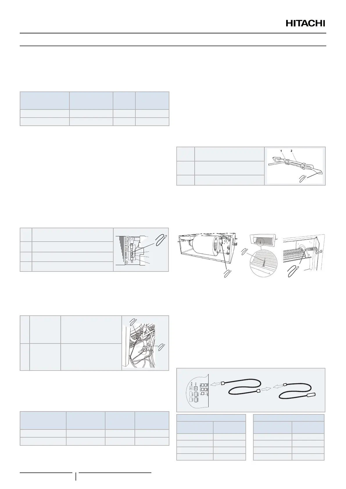
Thermistor installation example
1
Liquid / gas pipe thermistor (factory
supplied)
2
3
4
1
2 Thermistor holder (eld supplied)
3 Thermistor lead wire (eld supplied)
4 Insulation (eld supplied)
! CAUTION
The thermistor must be installed properly in order to avoid water onto the
thermistor.
Typical installation location
A
Liquid pipe
thermistor
Must be installed in the
coldest liquid line point in
the heat exchanger
(prior the distributor).
A
B
B
Gas pipe
thermistor
Must be installed as close
as possible to the heat
exchanger refrigerant
outlet.
Air thermistor
Two air thermistors are supplied inside the control box. The
purpose and identication of each one is as follow:
Item
PCB socket
/ Thermistor
connector color
PCB socket
number
Thermistor
length (mm)
Inlet air thermistor Blue THM 1 1200
Outlet air thermistor Red THM 2 1200
! CAUTION
In case that the thermistors supplied with the DX-Interface are not long
enough, please make sure that the length extension is properly done
avoiding the sensing distortion and that the joint is properly insulated to
avoid any electrical failure.
? NOTE
When tting the air thermistor, remember that they must be secure
correctly, in an adequate place to avoid external inuences, like ambient
conditions, and where the air temperature is signicant.
Cable clamp example
1 Tie (Field supplied)
3
2
Cable clamp (Field supplied)
3 Thermistor (supplied)
! CAUTION
The thermistor must be installed properly in order to avoid water onto the
thermistor.
Typical installation
In case of modular outdoor unit installation, it is possible to install air
thermistors only to the DX-Interface set as “group controller”. The
thermistors locations must ensure then a proper reading of the air
temperature, representative of the total inlet or outlet air ows of the unit
to be controlled.
? NOTE
In case of simplied air thermistors installation, only one Remote
Controller can be connected within the DX-Interface gruped together and
connected to the same indoor unit (the installations of a second remote
controller is allowed only if it is set as “slave”)
Thermistor extension installation
B
A B
PCB socket
Thermistor
extension
Thermistor
extension
Thermistor
THM1 Blue Blue Blue
THM2 Red Red Red
THM3 Black Black Black
THM5 Yellow Yellow Yellow
 Loading...