ELECTRICAL WIRING
PMML0293A rev.2 - 08/2016
17
8.3 DIP SWITCH SETTINGS
8.3.1 Quantity and location of Dip Switches
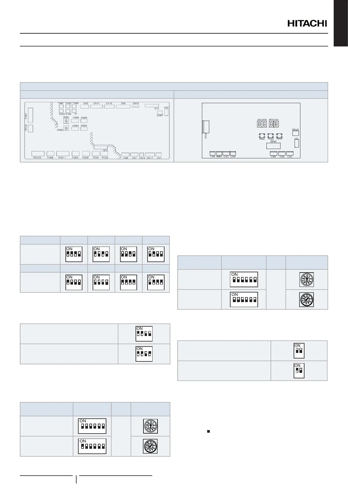
Dips switches are located in printed circuit boards of control box, as it is shown below:
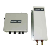
DX-Interface EXV-(2.0-10.0)E2: Control box
PCB1 PCB2
! CAUTION
Before setting DIP switches, rstly turn off power source and set the position of the dips switches. If the switches are set without turning off the power
source, the contents of the setting are invalid.
PCB1 settings
DSW3: Capacity code setting
No setting is required. This DIP switch is used to set the capacity
code corresponding to the DX-Interface power (HP).
HP 2.0 2.5 3.0 4.0
Factory setting
1
2
3 4
1
2
3 4
1
2
3 4
1
2
3 4
HP 5.0 6.0 8.0 10.0
Factory setting
1
2
3 4
1
2
3 4
1
2
3 4
1
2
3 4
DSW4: Unit model code setting and optional setting
No setting is required.
Factory setting
1
2
3 4
Enabled EC fan motor alarm by tach input
(Set pin 4 to ON position)
1
2
3 4
DSW5 and RSW2: Refrigerant cycle number setting
Setting is required. This switch is used to set the refrigerant
cycle number.
Refrigerant cycle
number example
DSW5 RSW2
00
(Factory setting)
1 2
3
4
5 6
+
16
1 2
3
4
5 6
DSW6 and RSW1: Unit number setting
Set DSW6 and RSW1 to modify the indoor unit address. The
setting must be made so that it does not overlap the setting of
other indoor units in the same refrigerant cycle. If the setting
is not made manually, the automatic address function will be
enable.
Set to a value of up to 63.
Unit number
example
DSW6 RSW1
00
(Factory setting)
1 2
3
4
5 6
+
06
1 2
3
4
5 6
DSW7 switch: Fuse recovery
No setting is required.
Factory setting
1
2
Fuse recovery (*1)
1
2
? NOTE
• (*1): In case of applying high voltage to the terminals 1 and 2 of
control connection (items 17 and 18 of TB2) the fuse on the PCB1
is cut. In such a case, rstly correct the wiring to TB1 and then turn
ON the pin 1.
• The mark indicates position of dips switches. Figures show setting
before shipment or after selection.
ENGLISH
 Loading...