DX-INTERFACE ALARM CODES
PMML0293A rev.2 - 08/2016
24
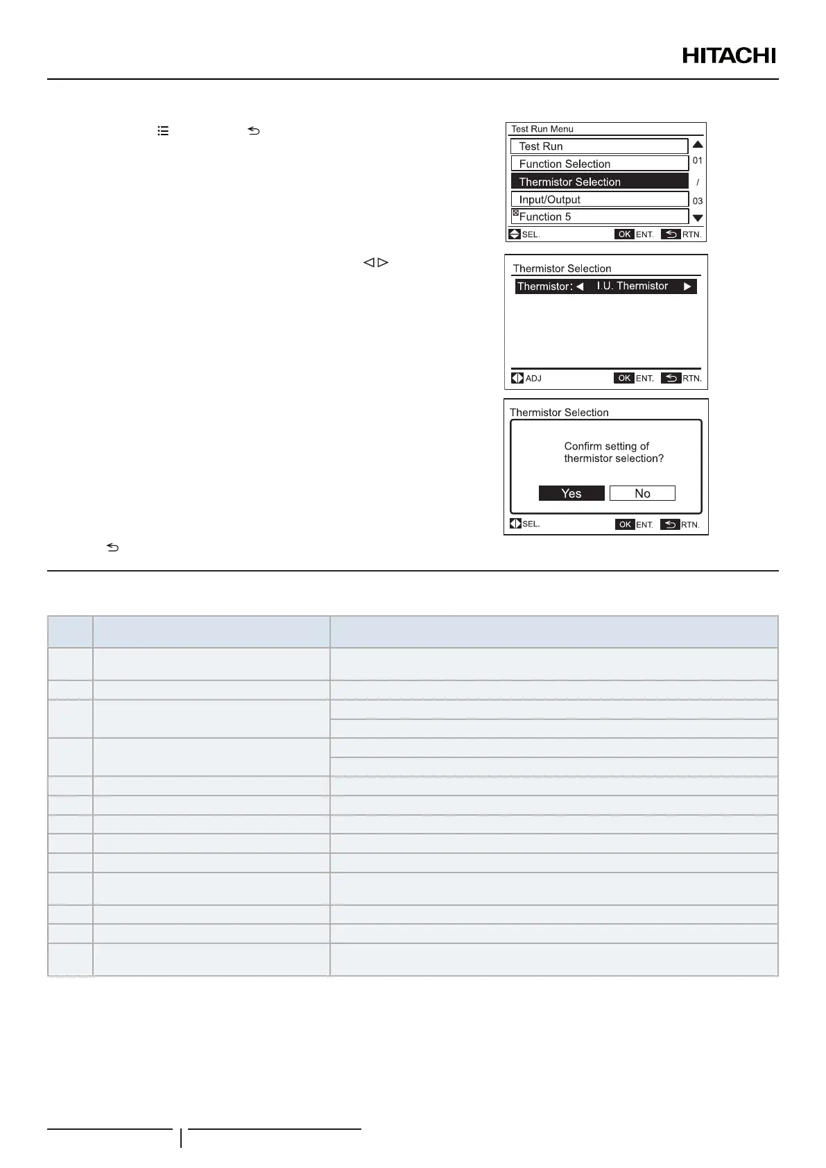
1 Press and hold “ ” (menu) and “ ” (return) simultaneously for
at least 3 seconds during the normal mode (when unit is not
operated). The test run menu will be displayed.
2 Select “Thermistor Selection” from the test run menu and press
“OK”.
3 Change the temperature thermistor item by pressing “ ” and
press “OK”.
• IU Thermistor: Control by inlet air thermistor (Factory setting)
• THM of RSCW: Control by thermistor of remote control switch
• Average of THM: Control by average value of indoor suction
thermistor and thermistor of remote control switch
4 Select “Yes” and press “OK”. The test run menu will be displayed
after the setting is conrmed. If “No” is pressed, the screen will
return to (3).
5 Press “ ” (return) on the test run menu to return to the normal mode.
13 DX-INTERFACE ALARM CODES
Alarm
Code
Detail of Abnormality Main Factors
01 Activation of protection device
Float switch activation (high water level in drain hose or abnormality in drain pipe, oat
switch or drain pan).
03 Transmission error with the outdoor unit. Outdoor fuse meltdown, Indoor/outdoor connection wiring (breaking, wiring error, etc.)
11 Air outlet thermistor
If IU as group controller: Loose, disconnected, broken or short-circuited connector
If IU as normal unit: no thermistor and no Group message received.
12 Air inlet thermistor
If IU as group controller: Loose, disconnected, broken or short-circuited connector
If IU as normal unit: no thermistor and no Group message received.
13 Liquid pipe thermistor Loose, disconnected, broken or short-circuited connector
14 Gas pipe thermistor Loose, disconnected, broken or short-circuited connector
19 Indoor fan protection device activation for Fan Fan motor overheating, locking.
31 Incorrect setting of outdoor and indoor units Outdoor/Indoor Unit capacity setting error, Indoor total capacity excessively large/small
35 Indoor Unit Number Setting Error Indoor units with the same number exist in a refrigerant piping system
70
Abnormal transmission between PCB1 and
PCB2
Loose, disconnected
71 Incorrect PCBs setting Wrong setting are performed in PCBs
73 Incorrect 4-20Ma, 0-10v, 0-5v, 0-10k Ω setting Loose, disconnected, broken or short-circuited connector
EE
Compressor protection alarm (cannot be reset
from the remote controller)
This alarm code is displayed when the following alarms are triggered three times within
six hours: 02,07,08,39,43 to 45, 47
? NOTE
Alarms with origin in Outdoor unit, compressor and system are explained in outdoor unit technical documentation.
 Loading...