Item Name Min Max Description
4 Cooling
fan
(intak
e)
5
5
The
ve intake fans on the front of the controller pull air into the
controller and distribute it across the controller components.
5 Cache
Path
Control
Adapter
(CPA)
1 4 The CPA uses the built-in switch to connect the VSDs to the
front-end directors, back-end directors, and the cache backup
memory. It distributes data (data routing function) and sends
hot-line signals to the VSD. The shared memory is located on the
rst CPA cache board in each cluster in the primary controller.
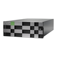
Figure 3 Controller, rear view
Table 6 Controller components, rear view
Item Name Min Max Description
1 Power
supply
2 4 200-240 VAC input. Provides power to the controller
chassis in a redundant conguration. Each power
supply contains two cooling fans to ensure constant
cooling if one fan fails.
2
Service
processor
(SVP)
1 2 A custom PC monitoring and controlling the storage
system. It contains the Device Manager - Storage
Navigator software, which congures and monitors
the system. Connecting the SVP to a service center
enables the storage system to be remotely monitored
and maintained by the support team.
System controller chassis
Chapter 2: Storage system hardware overview
Hitachi Virtual Storage Platform G1000, G1500, and VSP F1500 Hardware Guide 35

 Loading...